Push-and-pull type die turning-over device

A technology of push-pull and mold machine, which is applied in the direction of metal processing, etc. It can solve the problems of easy smashing of the workshop floor, impact tension of cranes, safety accidents, etc., and achieves the effect of simple structure

Inactive Publication Date: 2010-09-08
高鹏
View PDF0 Cites 0 Cited by
  • Summary
  • Abstract
  • Description
  • Claims
  • Application Information

AI Technical Summary

Problems solved by technology

When the mold is small, it can be turned over by a crane, but it is very dangerous to use a crane to turn over a medium and large mold. When a huge mold is overturned by a crane, it will hit the ground heavily and easily damage the workshop floor. , Break the mold, form impact tension on the crane, and even cause safety accidents. Therefore, it is necessary to have a mold turning equipment that can turn the mold over smoothly

Method used


Image

  • Push-and-pull type die turning-over device
  • Push-and-pull type die turning-over device
  • Push-and-pull type die turning-over device

Examples


Embodiment 1

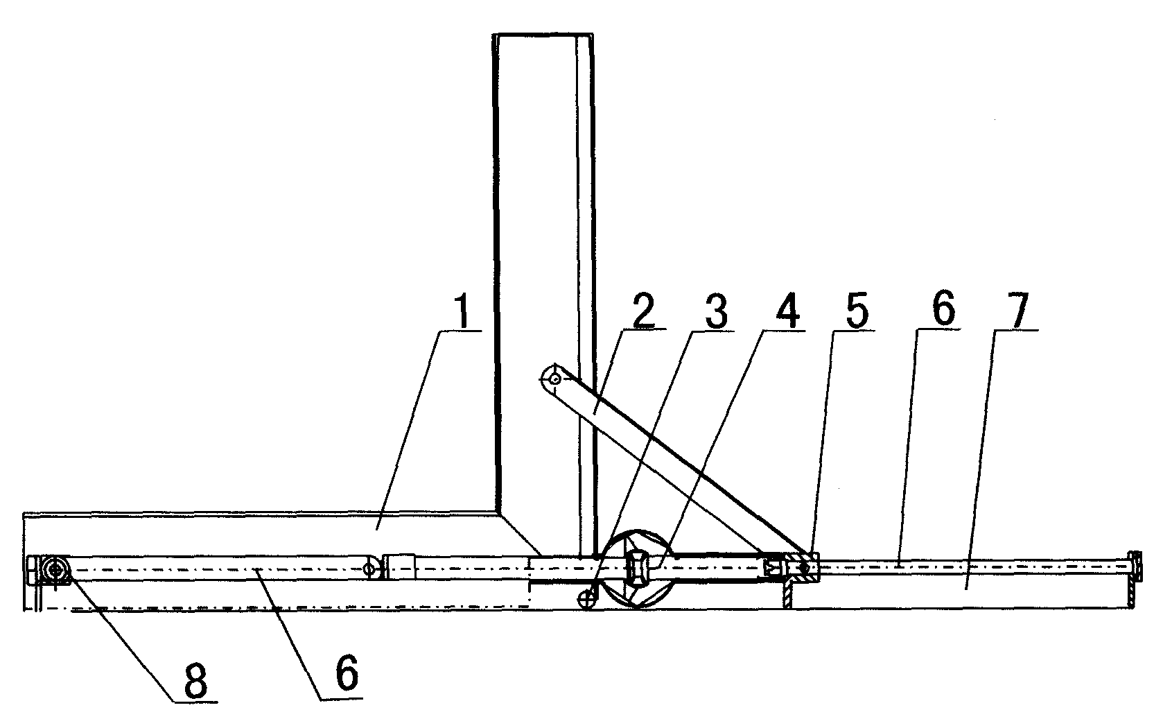
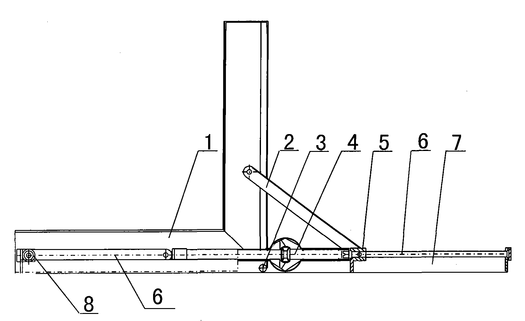
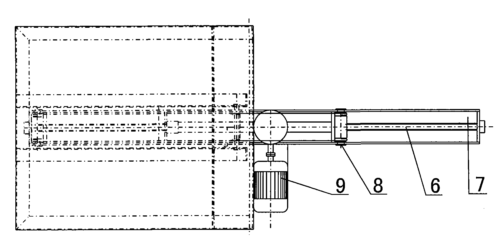
[0014] Embodiment 1: described push-pull type overturning machine comprises the overturning table body 1, chassis 7 that is used for placing and overturning mould, motor and differential gear are set on underframe 7, over underframe 7 and overturn mold Push-pull rods 2 are respectively arranged between the two sides of the table body 1, one end of the push-pull rod 2 is hinged with the turning table body 1, and the other end is connected with the nut 5, the nut 5 is arranged on the lead screw 6, and the lead screw 6 is horizontally arranged on the bottom On the frame 7, the leading screw 6 is connected with the differential 4. Load bearing wheels 8 are arranged on both sides of the nut 5. The load bearing wheels 8 are used to directly bear the weight of the mold on the chassis, so that the screw only bears the axial driving force to the nut and does not bear the weight pressure of the mold. Because the push-pull point of the push-pull rod 2 is closer to the rotating shaft and ...

Embodiment 2

[0015] Embodiment 2: It is basically the same as the main body structure in the embodiment, the difference lies in the structure of the lead screw and the push-pull rod. The screw rod is a swing screw rod 13, which can move up and down along with the movement of the push-pull rod. The push-pull rod includes an upper pull rod 12 and a lower pull rod 11, and a hinge nut 10 is arranged between the upper and lower pull rods. One end of the leading screw 6 is connected to the hinge nut 10, the other end is connected to the differential 4, the upper end of the upper pull rod 12 is hinged to the turning table body 1, the other end is hinged to the hinge nut 10, and the upper end of the pull rod 11 is hinged to the hinge nut 10. The lower end and the chassis 7 are hinged. Because the push-pull point of the push-pull rod is far away from the rotating shaft and the push-pull force is relatively large, it is suitable for turning over heavy molds, but its structure is slightly more compl...


PUM


Abstract

The invention discloses a push-pull mold overturning machine, which comprises a mold overturning table body (1) used for placing and overturning a mold and an underframe (7); the underframe (7) is provided with a motor (9) and a differential (4); two sides of the mold overturning table body are symmetrically provided with push-pull rods; one end of each push-pull rod on each side is connected with the mold overturning table body (1), while the other end is connected with a nut which is arranged on screw rods; the screw rods are connected with the differential (4); and during work, the motor (9) drives the differential (4), the differential (4) drives the screw rods on both sides, the screw rods drive the nut, the nut drives the push-pull rods, and the push-pull rods at one side pull and the push-pull rods at the other side push to drive the mold overturning table body to realize 90-degree overturning. The differential realizes distribution of moving speed and torque at both sides; andas the relationship between the screw rods and the nut, the machine has the self-lock function. The machine has the advantages of having simple and reasonable structure and low cost, and being capable of stably overturning heavy molds or other heavy devices which are put on the machine.

Description

technical field [0001] The invention belongs to an auxiliary device capable of turning a large mold by 90°, and mainly relates to a push-pull mold turning machine, which is used in the manufacture, use and maintenance of large and heavy molds. Background technique [0002] In the manufacturing industry, with the continuous development of large-scale molded parts, large-scale equipment and large molds are constantly upgraded, and the injection molds that occupy the first place in the mold and the die-casting mold that occupy the third place have developed into a set of molds It is very common to weigh tens of tons, and several tons or tens of tons. Since these two types of molds need to be placed horizontally (referring to the parting surface) during manufacture and maintenance, and must be placed vertically during use, it is necessary to frequently turn over the mold. When the mold is small, it can be turned over by a crane, but it is very dangerous to use a crane to turn o...

Claims


Application Information

Patent Timeline
Patent Type & Authority Patents(China)
IPC IPC(8): B23Q7/00
Inventor 高鹏张晓妍
Owner 高鹏
Why Eureka
Try Eureka