Device and method for impedance matching and bias compensation for difference transmission lines

A differential transmission line and impedance matching technology, applied in the field of communication transmission, can solve the problems of high power consumption of the system, large bias current at the signal sending end, and signal receiving end, etc., achieve small circuit power consumption, stable impedance, and avoid excessive bias The effect of setting the current

Inactive Publication Date: 2009-09-09
ZTE CORP
View PDF2 Cites 14 Cited by
  • Summary
  • Abstract
  • Description
  • Claims
  • Application Information

AI Technical Summary

Problems solved by technology

However, in the second prior art, the matching resistors Ra and Rc are all for matching the impedance on the transmission line, and the resistance is generally selected at about 60 ohm, which is too small, and at the same time, because the matching resistor is directly connected to the power supply or ground, thus Make the bias current of the signal sending end and the signal receiving end too large, which will cause excessive power consumption of the system

Method used


Image

  • Device and method for impedance matching and bias compensation for difference transmission lines
  • Device and method for impedance matching and bias compensation for difference transmission lines
  • Device and method for impedance matching and bias compensation for difference transmission lines

Examples


Embodiment Construction

[0032] The present invention will be described in further detail below through specific embodiments and accompanying drawings.

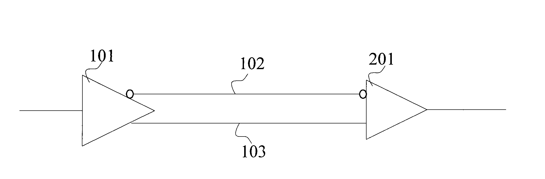
[0033] Figure 4 It is a schematic circuit diagram of the differential transmission line impedance matching and offset compensation device of the present invention. see Figure 4 The differential transmission line circuit includes a signal sending device 101 with two signal sending ends and a signal receiving device 201 with two signal receiving ends, and also includes two transmission lines, the first transmission line 102 connects the first signal sending end and the first signal receiving end, The second transmission line 103 connects the second signal sending end and the second signal receiving end. The impedance matching and offset compensation device has an offset compensation circuit 104 connected across the two transmission lines, and an impedance matching circuit 105 connected across the two transmission lines close to the signal sending d...


PUM


Abstract

The invention discloses a device and a method for impedance matching and bias compensation for difference transmission lines, wherein the device comprises a first transmission line connected with a first signal transmitting end and a first signal receiving end, a second transmission line connected with a second signal transmitting end and a second signal receiving end, a bias compensation circuit bridged over the two transmission lines, and an impedance matching circuit bridged over the two transmission lines and close to the signal sending end. The bias compensation circuit comprises a first resistor connected between an input voltage and the first transmission line, a second resistor connected between the first transmission line and the second transmission line, and a third resistor connected between the second transmission line and a ground wire; and the impedance matching circuit comprises a matching resistor and a matching capacitor which are connected together in series, wherein the matching resistor is connected with the first transmission line, and the matching capacitor is connected with the second transmission line. With the device and the method, the quality and the accuracy of signal transmission as well as the stability of data transmission of the difference transmission lines can be ensured with lower system power consumption.

Description

technical field [0001] The invention relates to communication transmission technology, in particular to an impedance matching and offset compensation device and method for a differential transmission line used to transmit communication signals. Background technique [0002] Differential transmission lines are used to transmit data over long distances. The transmission physical layer lines of differential transmission lines usually use twisted pair transmission or balanced transmission lines. The signal line groups required for signal transmission include: data signal positive terminal (SIG+) and data signal negative terminal (SIG-), positive terminal and negative terminal cancel the transmission crosstalk between each other. [0003] figure 1 It is a basic transmission diagram of a differential transmission line. see figure 1 , the signal sending device 101 transmits the data signal from the transmission lines 102, 103 to the signal receiving device 201 in a differential...

Claims


Application Information

Patent Timeline
Patent Type & Authority Applications(China)
IPC IPC(8): H04L25/02H04B14/06
Inventor 徐高峰贺席兵李刚健
Owner ZTE CORP
Why Eureka
Try Eureka