Adaptable antenna system

A technology for antennas and wireless communication equipment, which is applied in the field of communication to achieve optimal performance and reduce the cost and size of antennas

Active Publication Date: 2009-09-09
QUALCOMM INC
View PDF3 Cites 32 Cited by
  • Summary
  • Abstract
  • Description
  • Claims
  • Application Information

AI Technical Summary

Problems solved by technology

Additionally, as the number of wireless standards (WWAN, WLAN, Bluetooth, UWB, FLO, DVB-H, etc.) and frequency bands (from about 410MHz to about 11GHz)

Method used


Image

  • Adaptable antenna system
  • Adaptable antenna system
  • Adaptable antenna system

Examples


Embodiment Construction

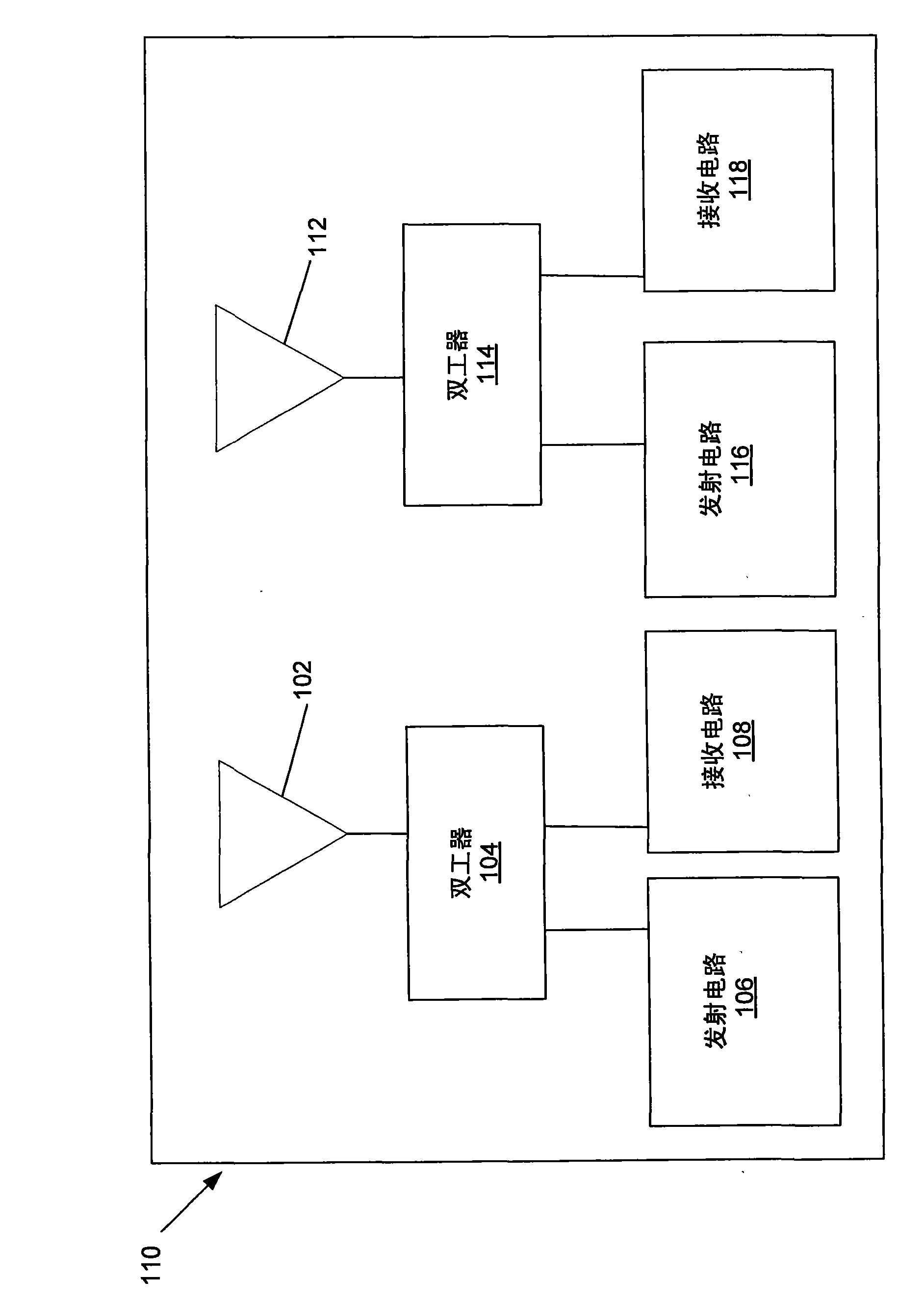
[0013] Some wireless communication devices, such as "world phones", wish to operate on multiple frequency bands ("multi-band") and multiple communication standards ("multi-mode"), and thus may require multi-frequency antennas and / or multiple The antenna is working normally. According to the laws of physics, to work in the required multiple frequency bands, a multi-frequency antenna must be larger than a single-frequency antenna. Such as figure 1 As shown, a "multi-band" device may use one transmit / receive antenna for each frequency band, thus having multiple transmit / receive antennas. Alternatively, a "multi-band" device may use one multi-band antenna, but requires the addition of multiplexers or single-pole multi-throw switches to route each band's antenna signal to the appropriate transmitter and receiver for each band.

[0014] Similarly, a "multimode" device may use one transmit / receive antenna for each communication standard and thus have multiple transmit / receive anten...


PUM


Abstract

The invention utilizes small, narrow-band and frequency adaptable antennas to provide coverage to a wide range of wireless modes and frequency bands on a host wireless device. The antennas have narrow pass-band characteristics, require minimal space on the host device, and allow for smaller form factor. The frequency tunability further allows for a fewer number of antennas to be used. The operation of the antennas may also be adaptably relocated from unused modes to in-use modes to maximize performance. These features of the antennas result in cost and size reductions. In another aspect, the antennas may be broadband antennas.

Description

technical field [0001] The present invention relates generally to the field of communications, and in particular to adaptive antenna systems. Background technique [0002] Wireless communication devices have different antenna requirements in next-generation wireless network systems. The specific antenna configuration needed to meet these requirements is influenced by many factors such as specific carrier requirements (e.g., mode of operation, frequency band class, required functionality) and device type (e.g., cell phone, desktop modem, laptop, PCMCIA card , PDA, etc.). In addition, as the number of wireless standards (WWAN, WLAN, Bluetooth, UWB, FLO, DVB-H, etc.) and frequency bands (from about 410MHz to about 11GHz) grows, traditional approaches require an increase in the host wireless device for new standards and / or new antennas for new frequency bands. This increases cost (for the antenna unit, associated cables and connectors), requires additional space on the wirele...

Claims


Application Information

Patent Timeline
IPC IPC(8): H01Q21/30H01Q5/00H01Q1/22
CPCH01Q21/28H01Q1/22H01Q9/145H01Q21/30H01Q5/00H01Q1/24
Inventor A·M-T·德兰E·T·奥萨基J·杰恩瓦达那卫特G·A·布赖特
Owner QUALCOMM INC
Why Eureka
Try Eureka