Fixing device for neutralizing actions between two vertebral bodies

A fixation device and intervertebral technology, applied in fixers, internal fixers, medical science, etc., can solve problems such as intervertebral disc degeneration and disease, metal fatigue, injury to nerve tissue, etc., to reduce the probability of metal fatigue or loosening , The effect of pressure load reduction

Active Publication Date: 2012-07-25
A SPINE ASIA
View PDF3 Cites 3 Cited by
  • Summary
  • Abstract
  • Description
  • Claims
  • Application Information

AI Technical Summary

Problems solved by technology

[0008] 2. See figure 1 and figure 2 As shown, driving the screw 20 into the pedicle 12 is very easy to damage the inner nerve tissue of the pedicle 12 during the operation, and cause degeneration and disease of the adjacent intervertebral disc in the future, so that the patient must undergo another operation
[0009] 3. See figure 1 and figure 2 As shown, since the metal rod 21 must fully bear the forces and torsional forces in six directions (forward bending, backward leaning, left-right tilting, and left-right torsion) between the vertebral bodies 101 and 102, and the said acting forces and torsion forces are transmitted through its The two screws 20 at the upper and lower ends are transmitted to the fixed points of the pedicle 12 driven into the screws 20, which can easily cause the loose bones in the vertebral bodies 101 and 102 to be unable to bear the huge unit force and torsion repeatedly, resulting in vertebral body fractures. The softer loose bone in 101, 102 cracks, thereby causing the screw 20 to loosen from the loose bone in the vertebral body 101, 102
[0010] 4. See figure 1 and figure 2 As shown, the force and torsion in the six directions on the metal rod 21 are borne by the extremely small cross-section of the screw 20, so it is very easy to cause metal fatigue due to long-term stress concentration, and then the screw 20 is between the metal rod 21 and the vertebral body. The junction of 101 and 102 breaks
[0011] Also, see image 3 As shown, the method of using the metal cage alone in the anterior or posterior approach does not have many problems caused by pedicle screws, but because the metal cage 31 is simply placed between the two adjacent vertebral bodies 301 and 302, according to According to biomechanical research, the pedicle screw system can effectively control the activities in six directions between the two adjacent vertebral bodies 301 and 302, while the independent metal cage 31 can only control the activities of left and right inclinations. For the other four directions ( Forward bending, backward tilting and left and right twisting) are all less controllable than pedicle screw system

Method used


Image

  • Fixing device for neutralizing actions between two vertebral bodies
  • Fixing device for neutralizing actions between two vertebral bodies
  • Fixing device for neutralizing actions between two vertebral bodies

Examples


Embodiment Construction

[0036] The present invention will be further described below in conjunction with the accompanying drawings and specific embodiments, but not as a limitation of the present invention.

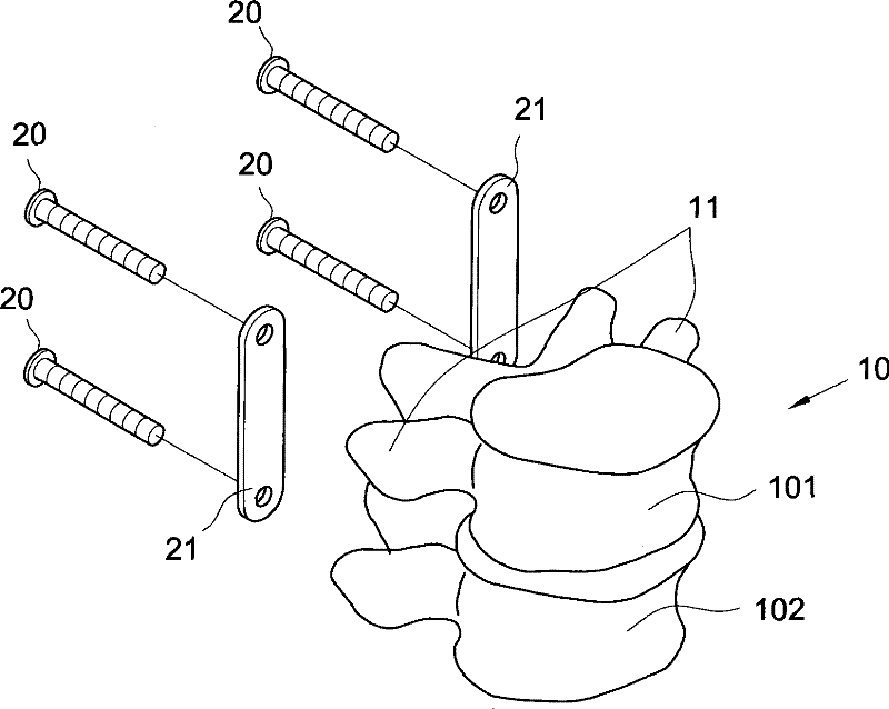
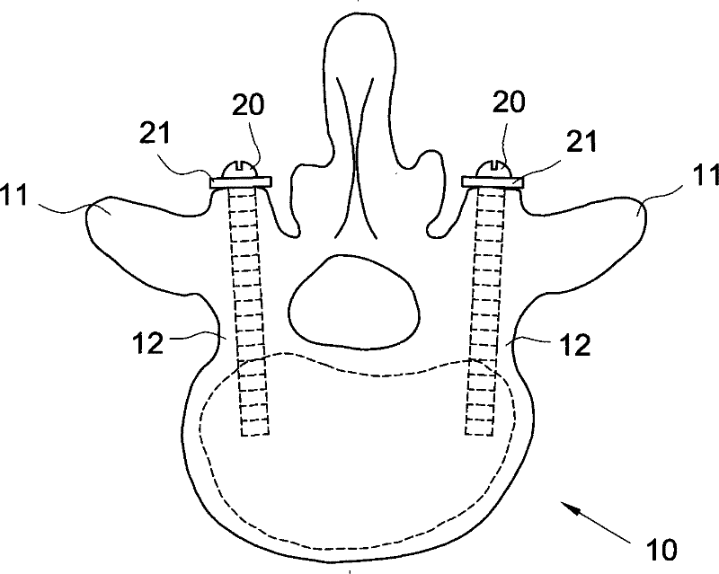
[0037] Such as Figure 4 , 5 The present invention shown in and 6 is a fixing device for neutralizing the movement between two vertebral bodies, which is applied between the vertebrae such as thoracic vertebrae, lumbar vertebrae, etc., so that two adjacent vertebral bodies can maintain a stable fixing device. The device 40 is a plate-shaped body, and one side of the plate-shaped body has a nail portion 41 (such as Figure 4 shown), for implanting the fixation device 40 into one or two corresponding vertebral bodies 501, 502 and the intervertebral disc 510 through the nail part 41, wherein the nail part 41 is selected from a double-sided thinning and a One of a kind thinned on one side.

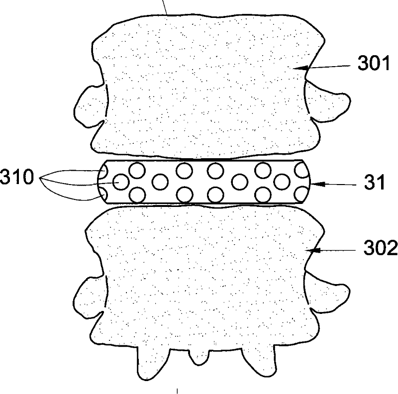
[0038] Further, the fixing device 40 can also be combined with a support assembly 70 (such as Figure 5 ,...


PUM


Abstract

The invention discloses a fixing device for neutralizing actions between two vertebral bodies, in particular a fixing device for neutralizing or countervailing actions between two adjacent vertebral bodies. The fixing device is a plate-shaped body, one side of the plate-shaped body is provided with a nail part, and the fixing device is embedded into two corresponding vertebral bodies and intervertebral discs by the nail part. When necessary, the fixing device also can be matched with a support assembly, such as a metal cage, and embedded into the intervertebral discs of the two corresponding vertebral bodies. Therefore, the fixing device can effectively control actions between the two vertebral bodies, such as forward bending, backward bending, left and right incline, left and right turn,and the like, and enable an autogenous bone embedded between the two adjacent vertebral bodies not to generate the problem of non-union or psuedarthrosis because of actions between the vertebral bodies before completely inosculated with the vertebral bodies.

Description

technical field [0001] The present invention provides a fixation device for neutralizing the movement between two vertebral bodies, especially applied between the vertebral bodies of two adjacent thoracic vertebrae, lumbar vertebrae...etc. Activities between adjacent vertebrae, such as bending forward, leaning back, tilting left and right, and twisting left and right, will cause problems such as poor fusion of the two vertebrae. Background technique [0002] Press, generally called "lumbar interbody fusion (interbody fusion)", which is mainly performed from the posterior (stripping the lumbar neural canal dura mater) or from the anterior (from the front of the abdomen to the front of the disc in the posterior abdominal cavity), First remove the degenerated intervertebral discs until there is no residual soft tissue between the two adjacent lumbar vertebrae, and then implant human bone (autologous or allogeneic) between the two adjacent lumbar vertebrae. After several months ...

Claims


Application Information

Patent Timeline
Patent Type & Authority Patents(China)
IPC IPC(8): A61B17/70A61B17/84A61L31/14
Inventor 林君甫
Owner A SPINE ASIA
Why Eureka
Try Eureka