LED optical-concentrated device in direct impact mode

A hedging, light-collecting technology, applied to lighting devices, lighting device parts, light sources, etc., can solve the problems of failing to achieve lighting effects, failing to reflect light, wasting the maximum energy of the light source, etc. The effect of improving light efficiency and easy maintenance

CN101581437AActive Publication Date: 2009-11-18TIGERFIRE GUANGZHOU LIGHTING TECH
0 Cites 2 Cited by

Patent Information

Authority / Receiving Office
CN · China
Current Assignee / Owner
Publication Date
2009-11-18

Smart Images

  • Figure 1
    Figure 1
  • Figure 2
    Figure 2
  • Figure 3
    Figure 3
Patent Text Reader

Abstract

The invention relates to an LED optical-concentrated device in direct impact mode, which comprises a shell, and a socket cover. The device has the characteristics that a reflector is clamped or sleeved on the inside of a lower opening of the shell; a circuit board is fixedly connected on the outside of the bottom of the reflector; an LED is arranged in the inner part of the reflector through a holder and the top direction of the LED is opposite to that of the opening of the reflector; and an LED is arranged in a direct impact mode on the inner bottom part of the reflector corresponding to the LED. The LED straightly faces a reflective panel of the reflector, an effective angle light intensity giving out by the LED shoots up forwardly through the spot light reflection of the reflective panel and an effective angle light intensity giving out by the other LED shoots up forwardly. Therefore, two light crosses overlay to enhance effects of facula, and can generate four states of simultaneously lighting, simultaneously dark, and single lighting of the two LEDs, which fully exerts the effects of light source and is applicable to the demands of different light intensity and lighting distance. The LED optical-concentrated device in direct impact mode is simple in structure, and convenient in maintenance, and can be widely used in various luminaries.
Need to check novelty before this filing date? Find Prior Art

Description

technical field

[0001] The invention relates to a light collecting device, in particular to a counter-type LED light collecting device. Background technique

[0002] In the existing traditional LED light-collecting devices in the form of reflectors, the LEDs are arranged facing the front. Since the light-emitting characteristics of the LEDs are that the light intensity in the front is the highest, the more they deviate from the positive axis, the lower the light intensity. Usually At the position of the cone angle of 120°, the light intensity is only half of the light intensity value directly in front. At this time, the light intensity on the reflector is not the maximum value of the LED, and the strongest light does not pass through the traditional form of collection. The reflector of the light device can be reflected, but it is only scattered naturally. Therefore, the reflector of the traditional forward-facing LED does not make full use of the maximum light intensity of t...

Examples

Embodiment Construction

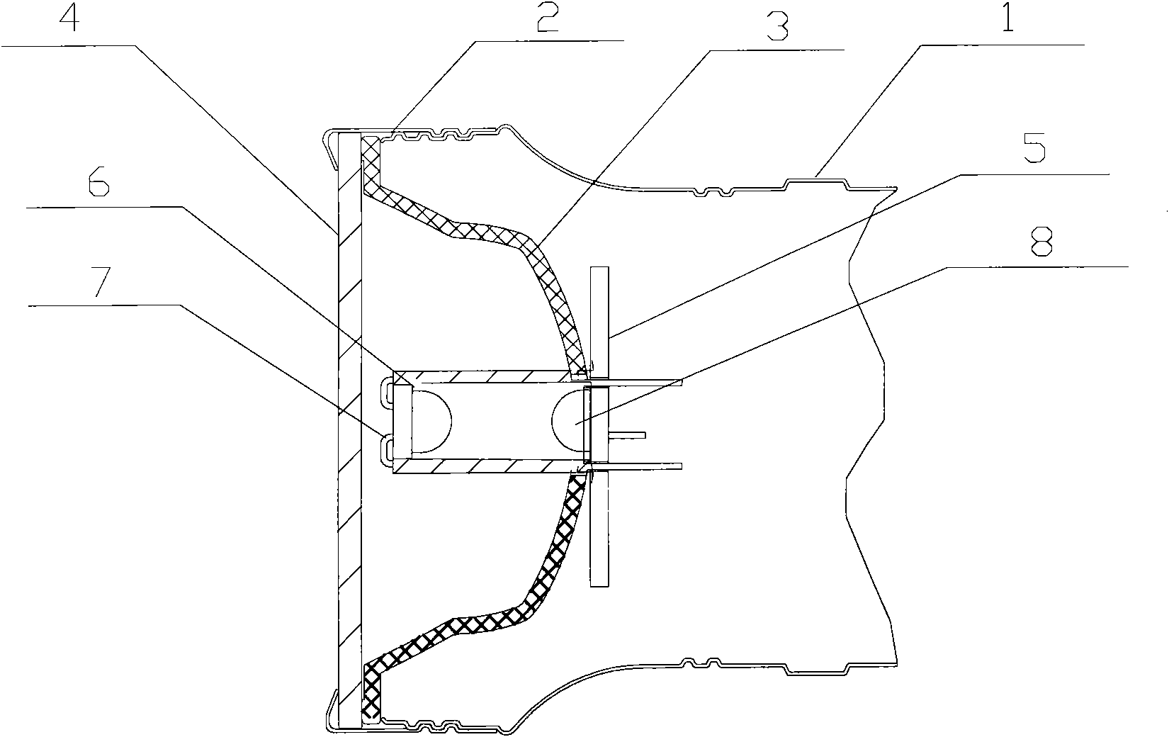
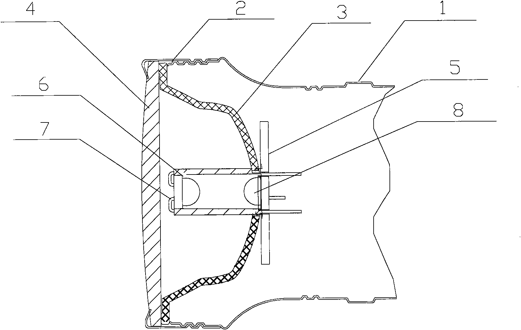
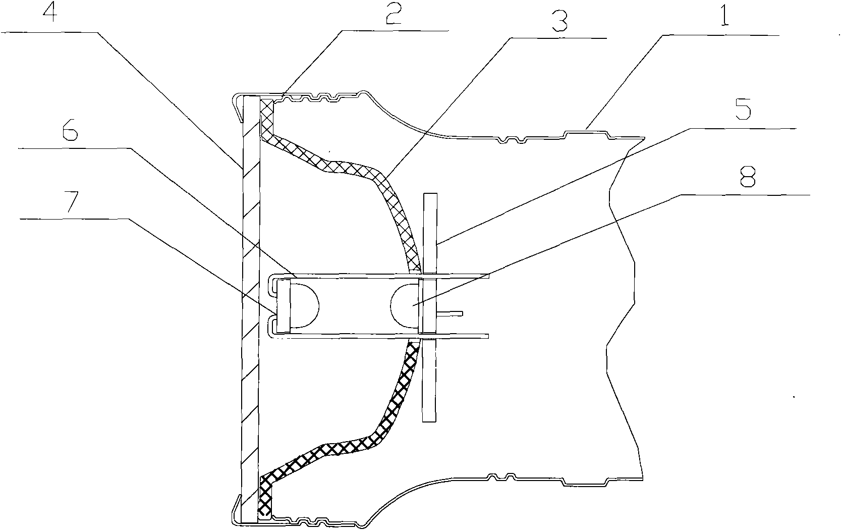
[0014] A hedging type LED light collection device, comprising a housing 1, a lamp cap 2, the lamp cap 2 is clamped or sleeved on the upper opening of the housing 1, the lower opening of the housing 1 is clamped or sleeved on the lamp body, and on the housing The inner side of the lower opening of 1 is clamped or socketed with a reflector 3, and a lens 4 is installed between the reflector 3 and the lamp cover 2; Install an LED7, the top direction of the LED7 is opposite to the opening direction of the reflector 3; the inside of the bottom of the reflector 3 and the corresponding position of the LED7 adopt a hedging type to install an LED8. The reflector 3 in the hedge type LED light collecting device is a double parabolic reflector, LED7 is installed on the focus of the inner parabola in the middle of the reflector 3, and LED8 is installed on the focus of the outer parabola on the reflector 3 periphery.

[0015] As another improvement of the present invention, the lens 4 in the...