Computerized numerical control machine tool and acceleration-deceleration method thereof

A numerical control and machine tool technology, applied in the direction of digital control, electrical program control, etc., can solve the problems of trajectory error, short acceleration distance, corner error, etc., achieve the effect of improving processing precision and product quality, and avoiding time delay

Active Publication Date: 2012-10-10
HONG QI MECHATRONICS ANHUI CO LTD +1
View PDF3 Cites 1 Cited by
  • Summary
  • Abstract
  • Description
  • Claims
  • Application Information

AI Technical Summary

Problems solved by technology

[0007] However, for using the moving average method, every time it is used, it will make the whole lag behind by twice the acceleration and deceleration time T1 (such as image 3 shown), and curves A, B, and C are the speed curves after the first, second, and third moving average methods respectively, that is, the machine tool will reach stability after three times the acceleration and deceleration time T1 action, and the shape of the speed curve cannot be changed according to the processing conditions, even if the speed curve after three times of use must be a bell-shaped curve (such as Figure 2C and image 3 As shown), so there is no other flexibility except for setting the acceleration and deceleration time T1. In addition, this method will produce a corner error and make the E part of the jerk curve sharper ( Figure 4 Shown), even because the acceleration distance is too short, resulting in the inability to accelerate to the highest speed, resulting in trajectory error

Method used


Image

  • Computerized numerical control machine tool and acceleration-deceleration method thereof
  • Computerized numerical control machine tool and acceleration-deceleration method thereof
  • Computerized numerical control machine tool and acceleration-deceleration method thereof

Examples


Embodiment Construction

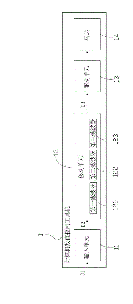
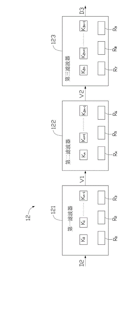
[0025] Please refer to Figure 5 As shown, the computer numerical control machine tool 2 in this embodiment includes an input unit 21 , a control unit 22 , a storage unit 23 , a drive unit 24 , a motor 25 and a processing platform 26 .

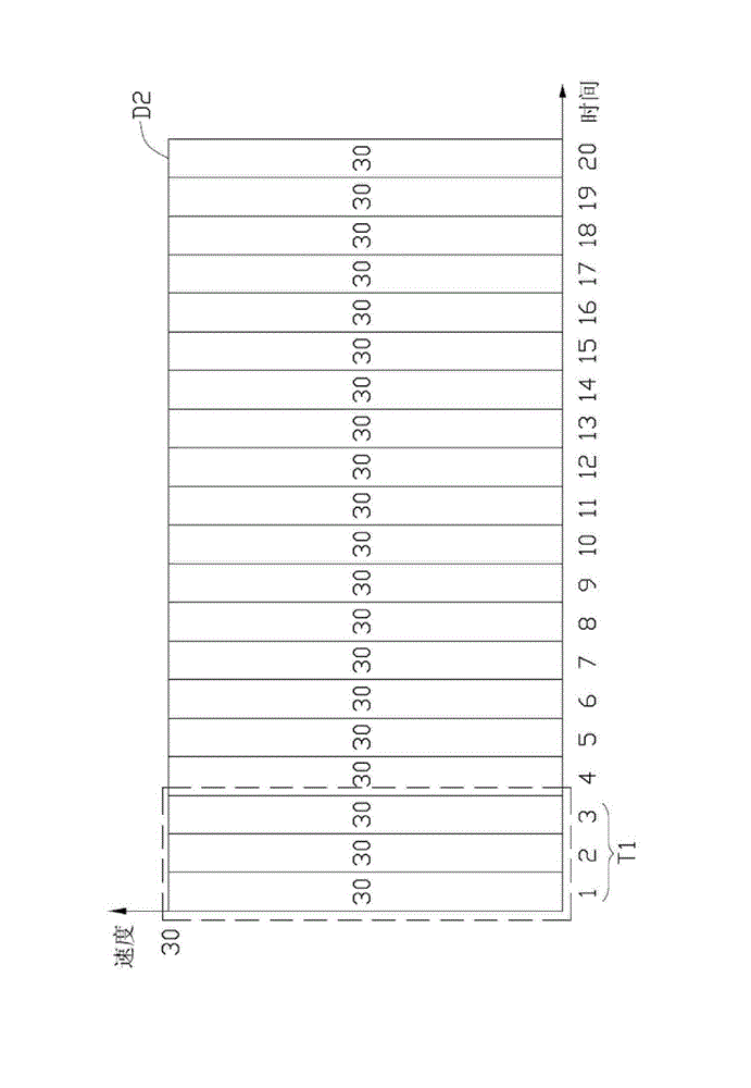
[0026] The input unit 21 receives an acceleration and deceleration time signal D4 and a speed signal D5, and the speed signal D5 is a tangential velocity signal (such as Image 6 shown), the acceleration and deceleration time signal D4 is divided into several sampling times (such as Figure 7 and Figure 8 shown); in addition, the acceleration and deceleration time signal D4 and the speed signal D5 can be set by the user, externally input or preset inside the computer numerical control machine tool 2.

[0027] Please refer to Figure 5 , Figure 7 and Figure 8 As shown, the control unit 22 is coupled to the input unit 21, which has a first function F1 and a second function F2. After the control unit 22 receives the acceleration and decel...


PUM


Abstract

The invention relates to an acceleration-deceleration method for a computerized numerical control machine tool, which comprises the following steps: recieving an acceleration-deceleration time signal and a speed signal; obtaining dissimilar first weight value and second weight value by the acceleration-deceleration time signal through a first function and a second function; judging whether a speedvariation of the speed signal is zero, a positive value or a negative value; outputting the speed signal when the speed variation is zero; obtaining an acceleration signal by the product of the speedsignal and the first weight value when the speed variation is the positive value; obtaining an deceleration signal by the product of the speed signal and the second weight value when the speed variation is the negative value; and converting the speed signal, the acceleration signal and the deceleration signal into a first driving signal, a second driving signal and a third driving signal respectively. The acceleration-deceleration method for the computerized numerical control machine tool of the invention can achieve the effect of a thrice moving average method only by once acceleration-deceleration plan, effectively control the jerk and the acceleration-deceleration time signal, and improve the product quality.

Description

technical field [0001] The invention relates to a machine tool and its acceleration and deceleration planning method, in particular to a computer numerical control machine tool and its acceleration and deceleration method. Background technique [0002] With the advancement of science and technology, as far as tool machinery is concerned, it has changed from numerical control (Numerical Control) technology to computerized numerical control (Computerized Numerical Control) technology. Numerical Control System) combines the mechanical action of the machine tool, and controls the movement control of the machine tool to the workpiece by inputting data codes. Due to the increasing functional requirements for the machine tool system, in addition to the computer volume and drive equipment It is also expected to be more and more precise as it becomes smaller, so the planning technology for increasing the acceleration and deceleration speed is one of the key items of computer numerica...

Claims


Application Information

Patent Timeline
Patent Type & Authority Patents(China)
IPC IPC(8): G05B19/416
Inventor 徐伟明邱志豪
Owner HONG QI MECHATRONICS ANHUI CO LTD
Why Eureka
Try Eureka