Square rotary ultrasonic motor oscillator

An ultrasonic motor, square technology, applied in generators/motors, electrical components, piezoelectric effect/electrostrictive or magnetostrictive motors, etc., can solve problems such as restricted mechanical output capability, and achieve flexible design and performance. Stable, efficient electromechanical coupling effect

Inactive Publication Date: 2012-03-14
HARBIN INST OF TECH
View PDF4 Cites 0 Cited by
  • Summary
  • Abstract
  • Description
  • Claims
  • Application Information

AI Technical Summary

Problems solved by technology

[0004] In order to solve the problem that the mechanical output capability of the stator of the ultrasonic motor that is excited by pasting the piezoelectric ceramic sheet with the metal elastic body is restricted, a square rotating ultrasonic motor vibrator is proposed.

Method used


Image

  • Square rotary ultrasonic motor oscillator
  • Square rotary ultrasonic motor oscillator
  • Square rotary ultrasonic motor oscillator

Examples


specific Embodiment approach 1

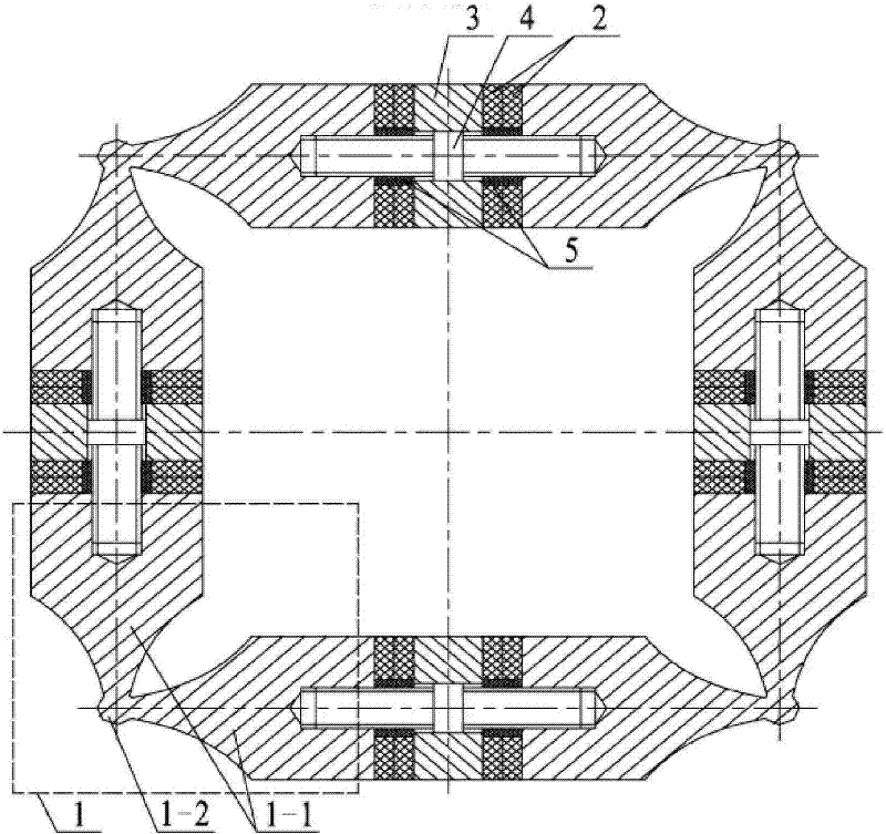
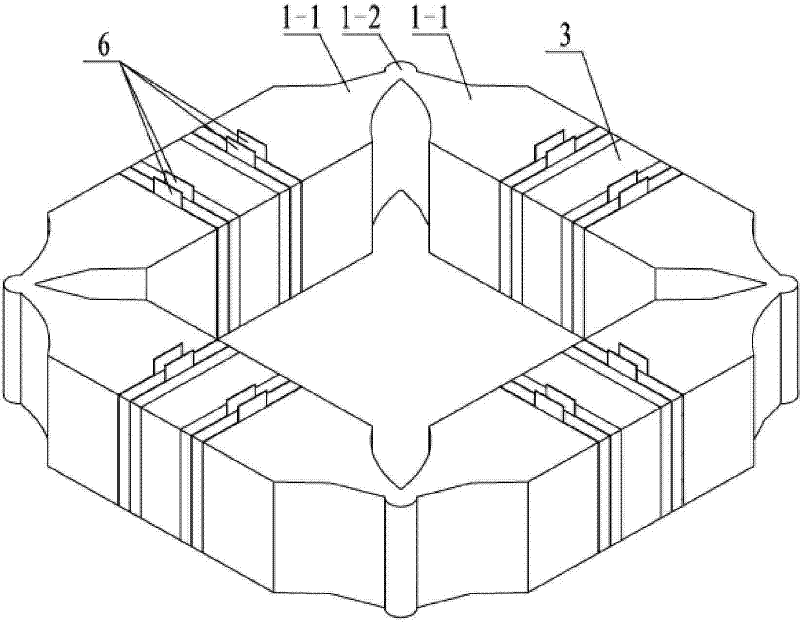
[0009] Specific implementation mode one: combine Figure 1 to Figure 4 Describe this embodiment, this embodiment is composed of four front end covers 1, eight pairs of piezoelectric ceramic sheets 2, four flanges 3, four pre-tightening studs 4, eight insulating sleeves 5 and eight pairs of electrode sheets 6; The structure and shape of the four front end covers 1 are the same; the front end cover 1 is composed of two horns 1-1 with the same shape and specifications and a driving foot 1-2, and the horn 1-1 is The cross-section is a rectangular prism that gradually becomes thinner. There is a blind hole with an internal thread at the center of the end face of the large end face of the horn 1-1. The threaded holes on the two adjacent horns 1-1 are The thread direction is opposite, the driving foot 1-2 is a cylinder, the small end faces of the two horns 1-1 are connected with the outer circumference of the driving foot 1-2 at the same time, the central axes of the two horns are p...

specific Embodiment approach 2

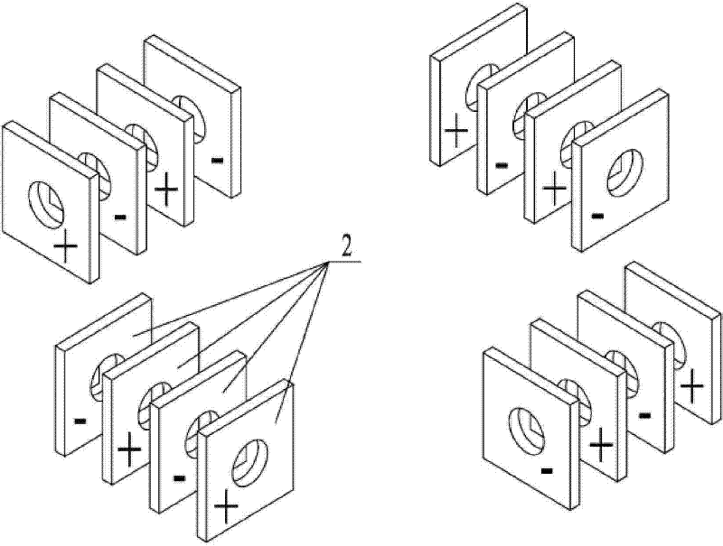
[0010] Embodiment 2: The difference between this embodiment and Embodiment 1 is that the polarization directions of every two adjacent piezoelectric ceramic sheets in the piezoelectric ceramic sheet 2 are opposite. Other composition and connection methods are the same as those in the first embodiment.

specific Embodiment approach 3

[0011] Embodiment 3: The difference between this embodiment and Embodiment 1 is that the cross-section of the piezoelectric ceramic sheet 2 is square or circular. Other composition and connection methods are the same as those in the first embodiment.


PUM


Abstract

The invention discloses a square rotary ultrasonic motor oscillator, which relates to an ultrasonic motor oscillator and aims at solving the problem that mechanical output capacity of the prior ultrasonic motor stator is limited. The square rotary ultrasonic motor oscillator consists of four front end covers, eight pairs of piezoelectric ceramics, four flanges, four pretightening studs, an insulating sleeve and an electrode plate, wherein each front end cover comprises two amplitude rods and a drive foot, the drive foot is a cylinder, two amplitude rods are orthogonally arranged, the drive foot is connected with the small end surfaces of the two amplitude rods, and the amplitude rods and the drive foot are an integral component; the pretightening studs pass through a flange through a square hole at the centre of the flange and are fixedly connected with big end surfaces of the two adjacent amplitude rods through threads at the two ends, and a pair of piezoelectric ceramics is sleeved on the stud between the amplitude rods. Body central lines of four drive feet form four square angle points through crossing axial lines of the four pretightening studs, therefore, the invention can be applied to the manufacture field of the ultrasonic motor.

Description

technical field [0001] The invention relates to an ultrasonic motor vibrator, in particular to a rotating ultrasonic motor vibrator. Background technique [0002] Piezoelectric ultrasonic motor is a kind of piezoelectric ultrasonic motor that uses the inverse piezoelectric effect of piezoelectric ceramics to excite vibration in the ultrasonic frequency range in the elastic body, and forms a particle motion with a specific trajectory at a specific point or area on the surface of the elastic body, and then passes through the stator, The frictional coupling between the rotors converts the microscopic motion of the particle into the macroscopic motion of the rotor. It has the advantages of low speed and high torque, no need for a transmission mechanism, no electromagnetic interference, fast response, and self-locking when power is off. As a piezoelectric driver, it has Very wide range of applications. [0003] Due to the simplicity of the excitation principle and the simplicity...

Claims


Application Information

Patent Timeline
Patent Type & Authority Patents(China)
IPC IPC(8): H02N2/12
Inventor 陈维山刘英想石胜君刘军考
Owner HARBIN INST OF TECH
Why Eureka
Try Eureka