Convenient and fast constant-resistance type temporary support strut

A temporary support and constant resistance technology, which is applied in the direction of pillars/brackets, mining equipment, earthwork drilling and mining, etc., can solve the problems of long disassembly and assembly time, bulky volume, complicated operation, etc., achieve fast support and ensure construction Safe, easy-to-handle effects

Inactive Publication Date: 2010-08-04
HENAN POLYTECHNIC UNIV
View PDF0 Cites 12 Cited by
  • Summary
  • Abstract
  • Description
  • Claims
  • Application Information

AI Technical Summary

Problems solved by technology

[0004] In view of the above situation, in order to overcome the defects of the existing technology, the purpose of the present invention is to provide a more safe, reliable, convenient and convenient constant resistance temporary support pillar, which can effectively solve the problem of temporary support in the maintenance of roadway heading head and roof fall area. The complex operation, long disassembly and assembly time, low initial support force, bulky volume, high price and other problems restrict the development of temporary support for excavation roadways. The technical solution is to include outer columns, sleeves, rack columns and inner active There is a top plate on the upper end of the inner column, and there are fixed holes on the column body of the inner column. The inner column is installed in the rack column. There are pin holes on the outer wall of the rack column. The pins pass through the pin holes and the pins in a cross shape. The fixing hole on the inner column fixes the inner column and the rack column together. The rack column passes through the sleeve and is installed in the outer column. The lifting mechanism for lifting the rack column is fixed on the sleeve, and the sleeve is fixed on the outer column. On the lower part of the outer column there is a chassis, and the outer column is equipped with a brake on the lower part of the sleeve

Method used


Image

  • Convenient and fast constant-resistance type temporary support strut
  • Convenient and fast constant-resistance type temporary support strut
  • Convenient and fast constant-resistance type temporary support strut

Examples


Embodiment Construction

[0012] The specific implementation manners of the present invention will be described in detail below in conjunction with the accompanying drawings.

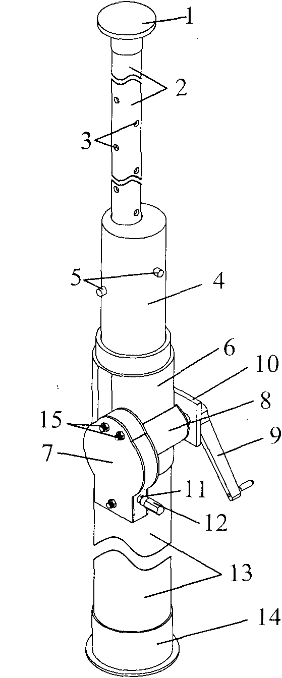
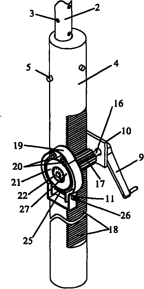
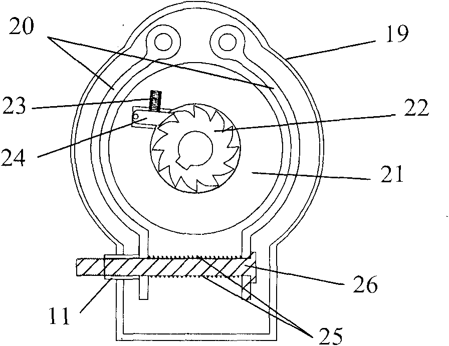
[0013] Depend on Figure 1-5 Shown, the present invention comprises outer column, sleeve, rack column and interior active column, and inner active column 2 upper end has top plate 1, and the column body of inner active column 2 has fixed hole 3, and inner active column 2 is contained in the gear In the bar column 4, pin holes are arranged on the outer wall of the rack column 4, and the pin 5 crosses in a cross shape through the pin hole and the fixing hole 3 on the inner column 2 to fix the inner column 2 and the rack column 4 together. The bar column 4 passes through the sleeve 6 and is installed in the outer column 13. The lifting mechanism for lifting the rack column 4 is fixed on the sleeve 6. The sleeve 6 is fixed on the outer column 13. There is a chassis 14 at the bottom of the outer column 13, and the outer column 13 A ...


PUM


Abstract

The invention relates to a convenient and fast constant-resistance type temporary support strut which can solve the difficulties restricting the development of tunneling temporary support in the tunneling temporary of maintenance of tunneling head and roof fall region maintenance, wherein the difficulties include complicated operation, long assembly and disassembly time, low setting stress, heavy size, high price and the like. In the structure, the temporary support strut comprises an outer strut, a sleeve, a rack strut and an inner movable strut; the inner movable strut is provided with a top tray at the upper end and fixing holes in the strut body and is installed in the rack strut; the outer wall of the rack strut is provided with pin holes; pins pass through the pin holes and the fixing holes in the inner movable strut in a cross way to fix the inner movable strut and the rack strut together; the rack strut passes through the sleeve and is installed in the outer strut; a lifting mechanism for lifting the rack strut up is fixed on the sleeve; the sleeve is fixed on the outer strut; a bottom tray is arranged at the lower part of the outer strut, and a brake is installed at the lower part of the sleeve on the outer strut. The convenient and fast constant-resistance type temporary support strut is light and adjustable, also has the advantages of high support speed, large support height, high setting stress, automatic pressure release and the like, and can greatly improve the filed working efficiency and guarantee the construction safety.

Description

1. Technical field [0001] The invention relates to temporary support equipment for roadway excavation in coal mines, in particular to a convenient constant resistance temporary support pillar used for temporary support during roadway excavation and roof fall area maintenance of mines and underground engineering thereof. 2. Background technology [0002] In the roadway excavation of mines and underground engineering, the temporary support device for the maintenance of the tunneling head and the roof fall area is an important part of ensuring safe construction. At present, the commonly used temporary support devices include: temporary support for the front probe beam, hydraulic temporary support, friction support, internal injection type single hydraulic support, etc., and the use of primary shotcrete as temporary support; but its operation is more troublesome and time-consuming to disassemble Long, heavy, low support height, poor reliability. It not only affects the speed of...

Claims


Application Information

Patent Timeline
Patent Type & Authority Applications(China)
IPC IPC(8): E21D15/20
Inventor 刘少伟王占民张辉许莉莉董士举张伟光郑新旺张鸿献师小永江永良姜永平
Owner HENAN POLYTECHNIC UNIV
Why Eureka
Try Eureka