Efficient high-strength composite drill bit

A composite drill bit, high-strength technology, used in construction and other directions, can solve the problems of cutting edge wear, blade wear and tear, affecting the construction quality of underground diaphragm walls, etc.

Inactive Publication Date: 2010-08-25
上海工程机械厂有限公司
View PDF3 Cites 8 Cited by
  • Summary
  • Abstract
  • Description
  • Claims
  • Application Information

AI Technical Summary

Problems solved by technology

[0003] In the prior art, the drill bits of multi-spindle drilling rigs generally adopt improved long helical drilling tools and drill bits, such as a new type of drilling tool, the patent number is ZL200720070011.2, which is fixed on the front end of the drill rod by two helical blades , The three-row cutter body is arranged crosswise and fixed on the bottom edge of the two helical blades, and the head of the cutter body is surfaci

Method used


Image

  • Efficient high-strength composite drill bit
  • Efficient high-strength composite drill bit
  • Efficient high-strength composite drill bit

Examples


Embodiment Construction

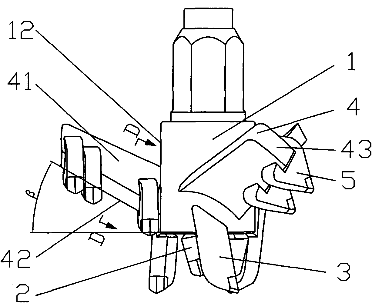
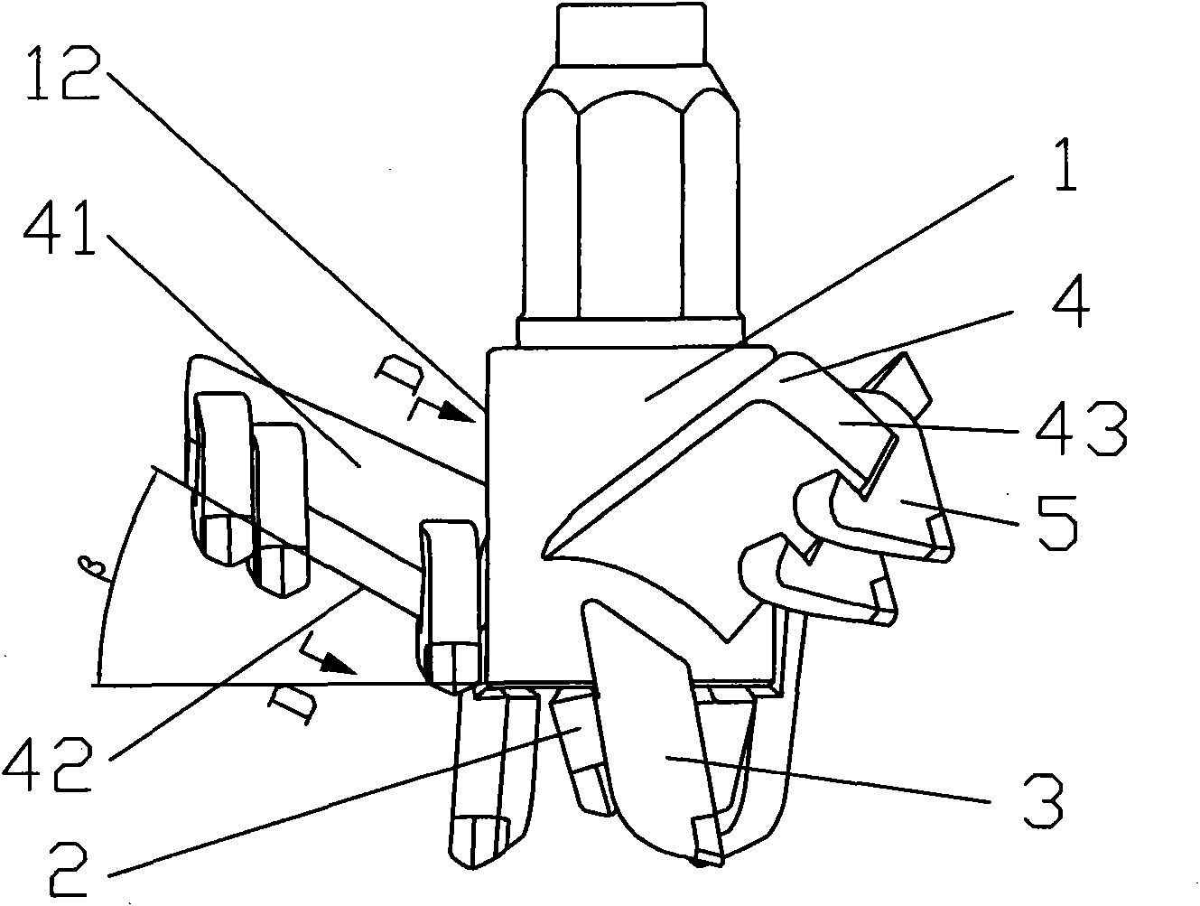
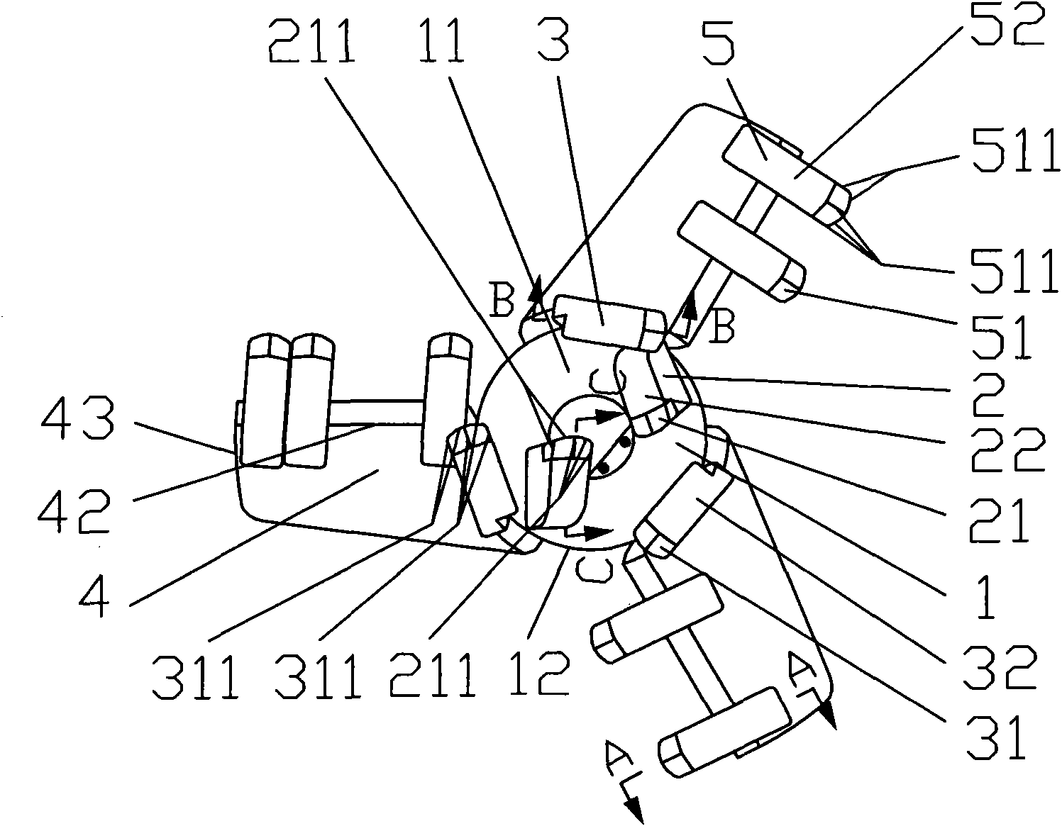
[0022] As shown in Figure 1, Figure 2, Figure 3, Figure 4, Figure 5 and Figure 6, a high-efficiency high-strength composite drill bit includes a drill pipe 1, a lower cutter body 2 composed of a lower cutter head 21 and a lower cutter handle 22, Inner cutter body 3, blade 4 made up of inner cutter head 31 and inner cutter handle 32, outer cutter body 5 made up of outer cutter head 51 and outer cutter handle 52; wherein, a through hole 11 is provided in the middle of the drill pipe 1 for cement Infusion of slurry; the lower cutter body 2 is fixed on the lower end of the drill pipe 1, there are 2 to 4 lower cutter bodies, the lower end of the rod body 1 is provided with a flange 13, and the installation direction of the lower cutter body 2 is to make the lower cutter head 21 is installed to face the direction of rotation of the drill pipe 1, and the lower handle 22 of the lower cutter body 2 is radially symmetrically welded and fixed on the lower end flange 13 of the drill pipe 1...


PUM


Abstract

The invention relates to a high-strength composite drill bit, which comprises a drill pipe, a lower cutter body consisting of a lower cutter head and a lower cutter handle, an inner cutter body consisting of an inner cutter head and an inner cutter handle, blades, and an outer cutter body consisting of an outer cutter head and an outer cutter handle, wherein the lower cutter body is fixed at the lower end part of the drill pipe, the inner cutter body is fixed on the periphery surface at the lower part of the drill pipe, the number of the blades is 2-4, and the blades are uniformly fixed in a radiation form on the periphery surface at the lower part of the drill pipe and are positioned above the inner cutter body; the outer cutter body is fixed on the blades; the lower cutter head in the lower cutter body, the inner cutter head in the inner cutter body and the outer cutter head in the outer cutter body are respectively welded together with the lower cutter handle, the inner cutter handle and the outer cutter handle; the front ends of the lower cutter head, the inner cutter head and the outer cutter head are respectively provided with a lower cutting edge, an inner cutting edge and an outer cutting edge; and the installation directions of the lower cutter body, the inner cutter body and the outer cutter body are the rotation directions which make the lower cutter head, the inner cutter head and the outer cutter head arranged towards the drill pipe. The working efficiency of the drill bit is multiplied, the combination strength of the cutter head and the cutter handle is high, the wear of the cutter head and a rib is slowed down, and the construction quality is ensured.

Description

technical field [0001] The invention relates to a high-efficiency and high-strength drill bit capable of penetrating strata, especially hard sand strata, and can be widely used in underground deep foundation projects such as underground facilities of high-rise buildings, foundation pit enclosure of subway stations, and reinforcement of river embankments. Background technique [0002] In the construction process of underground foundation projects such as urban high-rise buildings, deep foundation pit enclosure of subway stations, anti-seepage reinforcement of river dykes and soft soil foundation improvement and reinforcement, a large number of SMW construction method equipment is currently used to construct underground diaphragm walls, that is, multi-axis drilling rigs are used. The technology of continuously drilling, mixing soil and cement slurry in situ and inserting section steel to build underground retaining and waterproof walls, which plays the role of retaining soil an...

Claims


Application Information

Patent Timeline
IPC IPC(8): E21B10/55
Inventor 龚秀刚张国柱朱亚萍黄敏
Owner 上海工程机械厂有限公司
Why Eureka
Try Eureka