Electric valve control device capable of realizing intelligent control

An electric valve and control device technology, applied in valve devices, valve operation/release devices, valve details, etc., can solve the problems of not being able to control the network of the system, not having the function of signal acquisition and transmission, and independently controlling the body equipment, etc. Strong operability, improve application, improve the effect of intelligent control

Inactive Publication Date: 2010-09-08
SHENYANG ALUMINIUM MAGNESIUM INSTITUTE
View PDF0 Cites 5 Cited by
  • Summary
  • Abstract
  • Description
  • Claims
  • Application Information

AI Technical Summary

Problems solved by technology

Electric valves are generally installed on transmission pipelines, mainly to control the switching of gases, liquids, solids and other substances. The control of valves often needs to be interlocked with gas signals, liquid signals, material level signals, etc. or in some processes, The electric valve needs to be started in chain with other electrical equipment, etc. Therefore, the control signal of the electric valve must be collected on site to complete the control requirements of the electric valve and be able to be networked with the distributed control system (DCS) of the whole plant. The valve control device provided by the supplier does not have the function of signal acquisition and transmission, but only controls the main body equipment alone. The control system supporting the electric valve cannot realize electrical interlocking and cannot be networked with the control system of the whole plant. Therefore, a method that can quickly collect and drive electric valves is needed installation

Method used


Image

  • Electric valve control device capable of realizing intelligent control
  • Electric valve control device capable of realizing intelligent control

Examples


Embodiment Construction

[0016] The utility model will be further described below through the description of specific embodiments, but this is not a limitation of the utility model. Those skilled in the art can make various modifications or improvements according to the basic idea of ​​the utility model, but as long as they do not depart from this utility model The basic idea of ​​the utility model is all within the scope of the utility model.

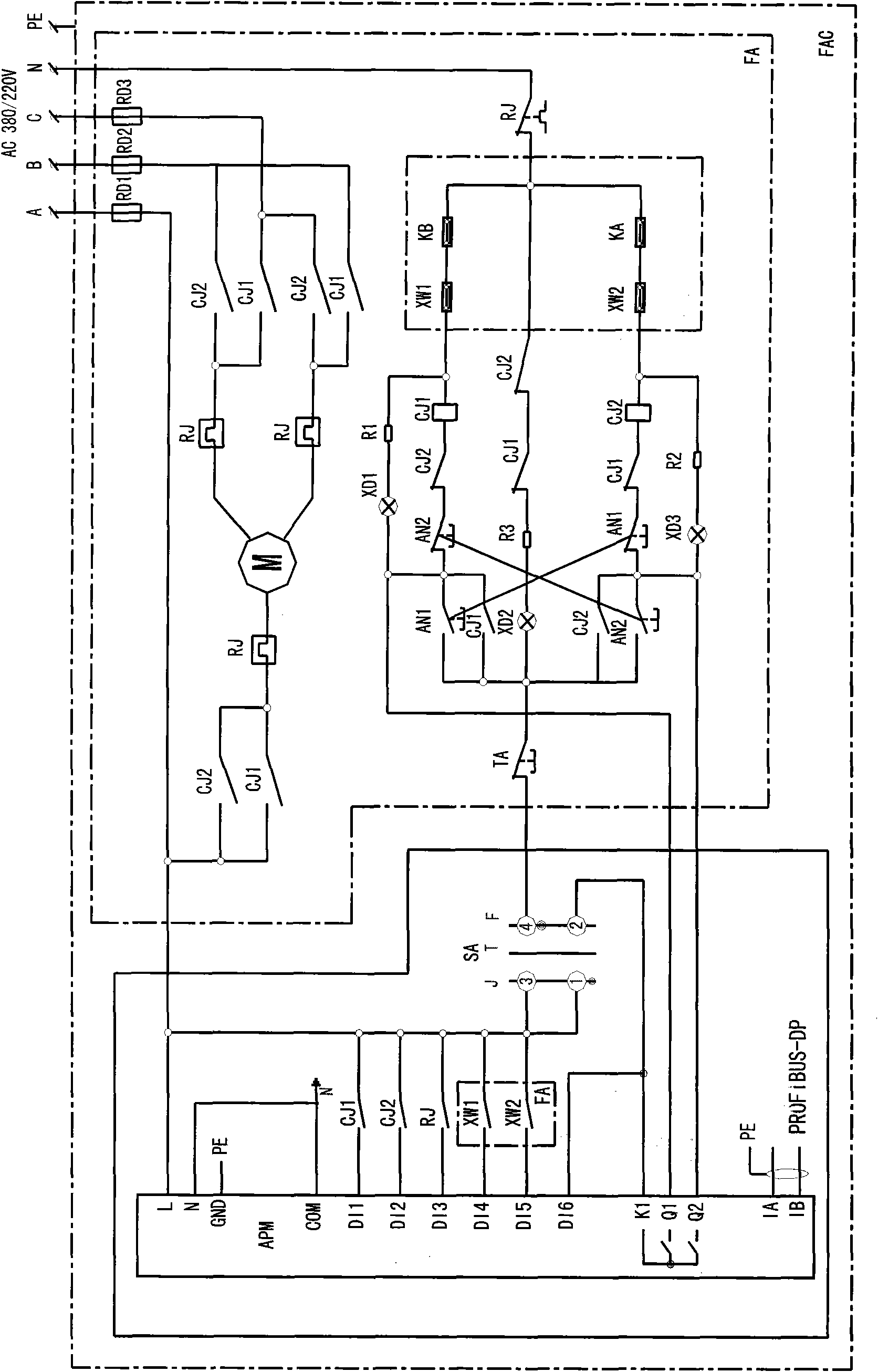
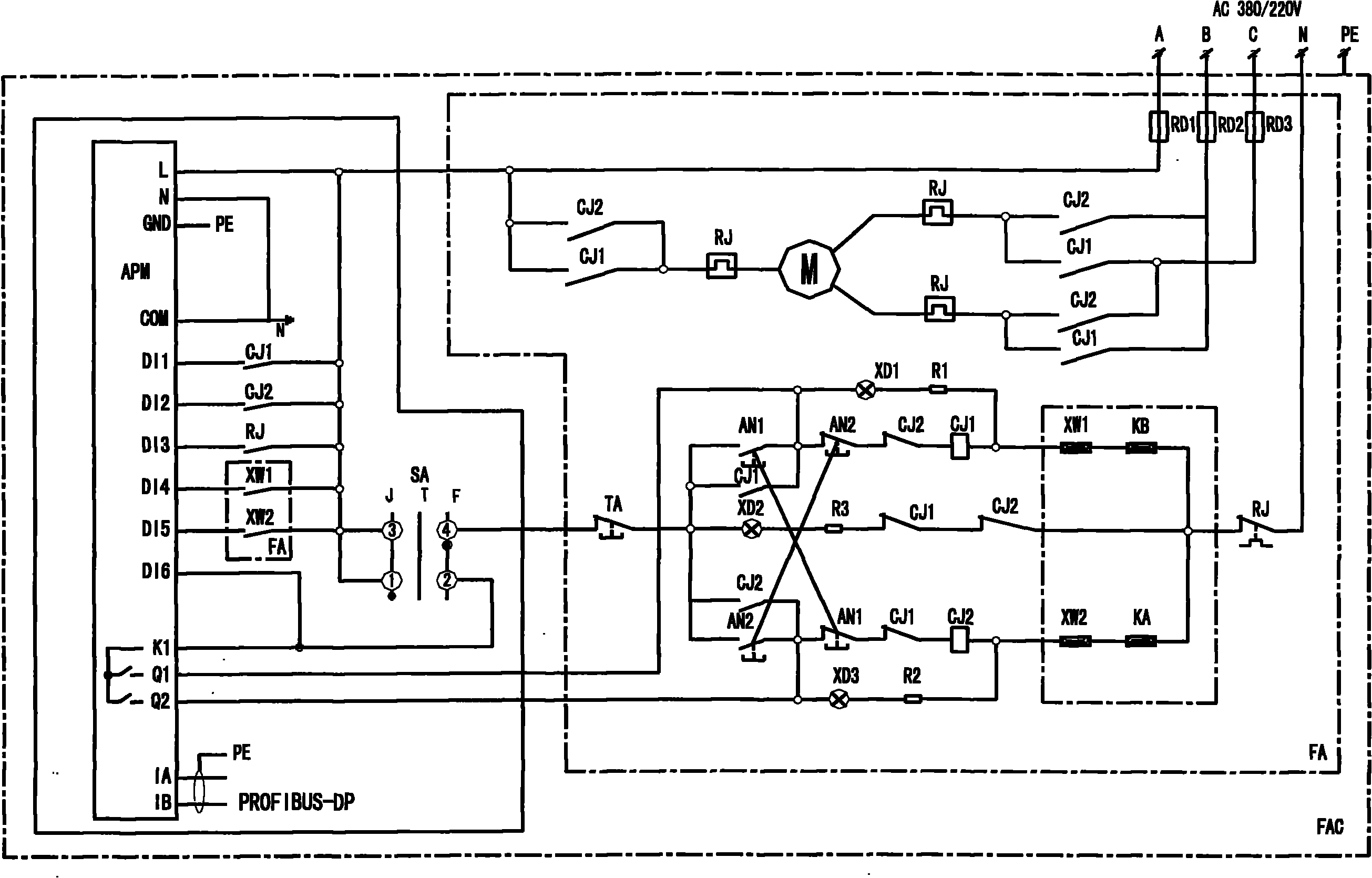
[0017] As shown in Figure 1, the present invention is an electric valve control device that can realize intelligent control. An intelligent motor protection controller 2 is added to the control box 1 of the existing electric valve, and an AC contactor CJ1 is installed in the control box 1. , CJ2, thermal relay RJ, travel switches XW1, XW2 and stop button TA, respectively connect the auxiliary contacts of AC contactors CJ1, CJ2, thermal relay RJ, travel switches XW1, XW2 to different parts of the intelligent motor protection controller 2 On the digital remote s...


PUM


Abstract

The invention discloses an electric valve control device capable of realizing intelligent control, which belongs to the technical field of automation control. One end of the auxiliary contacts of an AC contactor, a thermal relay and a travel switch is respectively connected on different switching value remote-signalling input terminals of an intelligent motor protection controller, a change-over switch is arranged between a stop button and the A phase of a power supply, a first terminal and a second terminal of the change-over switch are connected with the A phase of the power supply, a fourth terminal of the change-over switch is connected with one end of the stop button, the second terminal of the change-over switch is connected with one path of switching value remote-signalling input terminal of the intelligent motor protection controller and an output power supply control terminal, and a signal lamp of the intelligent motor protection controller is connected with a start button. The control of an electric valve realizes remote control and local control, and a control signal and a running signal of the valve can be transmitted by a communication mode, so that the valve can realize electric linkage control, and the running state of the valve can be monitored on an upper computer.

Description

technical field [0001] The invention relates to a valve control device, in particular to an electric valve control device capable of realizing intelligent control, which belongs to the technical field of automatic control. Background technique [0002] The electric drive valve is a commonly used drive mode valve, and the drive device of this drive form is usually called a valve electric device. The body control of this device has a separate control device, and the equipment manufacturer generally provides a complete set with the valve. Electric valves are generally installed on transmission pipelines, mainly to control the switching of gases, liquids, solids and other substances. The control of valves often needs to be interlocked with gas signals, liquid signals, material level signals, etc. or in some processes, The electric valve needs to be started in chain with other electrical equipment, etc. Therefore, the control signal of the electric valve must be collected on site...

Claims


Application Information

Patent Timeline
Patent Type & Authority Applications(China)
IPC IPC(8): F16K31/04
Inventor 王中杰郝娟戈光金
Owner SHENYANG ALUMINIUM MAGNESIUM INSTITUTE
Why Eureka
Try Eureka