Method for correcting heterogeneities in optical beam image transmission system

A technology of non-uniformity correction and optical fiber image beam transmission. It is applied in the direction of beam optical fiber, image enhancement, image data processing, etc. Effect

Inactive Publication Date: 2011-09-14
SHANGHAI INST OF TECHNICAL PHYSICS - CHINESE ACAD OF SCI
View PDF2 Cites 0 Cited by
  • Summary
  • Abstract
  • Description
  • Claims
  • Application Information

AI Technical Summary

Problems solved by technology

Due to the manufacturing process of fiber optic bundles, the overall transmittance of each level of fiber sub-bundles may have a large difference. If the traditional one-point method is used for correction, that is, the response of the fiber element is corrected to its average response, it will not be possible to correct the optical fiber in the image. the strip

Method used


Image

  • Method for correcting heterogeneities in optical beam image transmission system
  • Method for correcting heterogeneities in optical beam image transmission system
  • Method for correcting heterogeneities in optical beam image transmission system

Examples


Embodiment Construction

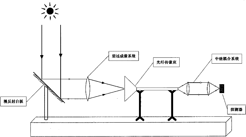
[0027] Taking the application of the present invention in a project based on line-plane conversion optical fiber image transmission beam system as an example, the specific implementation of the present invention will be described in detail below:

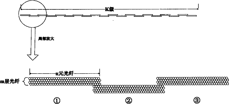
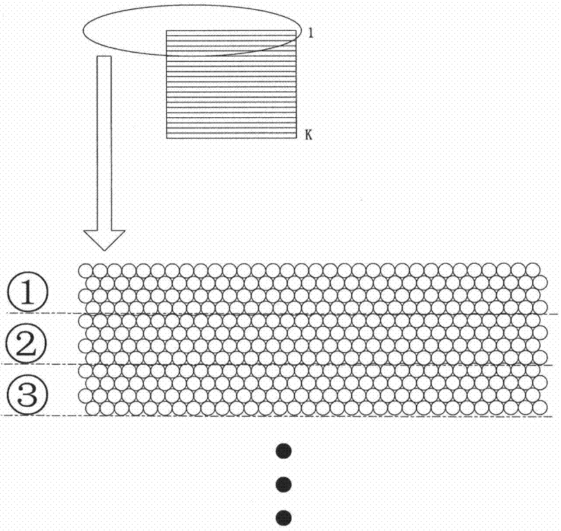
[0028] The arrangement structure of the optical fiber image transmission bundle in the project is as follows: the line array at the input end of the optical fiber bundle is arranged in a character shape with 40 levels of optical fiber sub-bundles dislocated and overlapped, and each level of optical fiber sub-bundles is closely arranged in 4 layers of 4×210 element optical fibers. The output end of the fiber bundle is arranged in a 210×160 element array. When recovering the scanned image, only the second layer of the 4-layer optical fiber is used, so the non-uniformity correction is only performed on the second-layer optical fiber of each level of fiber sub-bundle, so when it comes to a certain level of fiber sub-bundle, it refers to ...


PUM


Abstract

The invention discloses a method for correcting heterogeneities in a line-face conversion type optical beam image transmission system. The method is used for correcting in a photoelectrical system of an ultra-long line array detector for acquiring line-face conversion type optical beams by adopting a multi-section type graded one point method. After the method is used, the heterogeneities of images are obviously improved, thereby laying foundation for subsequent image analysis.

Description

technical field [0001] The invention belongs to the field of image processing of an optical fiber bundle image transmission system, in particular to a method for correcting non-uniformity in a line-plane conversion type optical fiber bundle image transmission system. Background technique [0002] The line array detector is a key component in the scanning imaging system, and the ultra-long line array can expand the scanning range and improve the system resolution. Ultra-long line array detectors worth more than 6,000 yuan are currently limited by the technology and cannot be achieved. The photoelectric imaging system composed of special-shaped optical fiber image transmission bundles can solve this problem (Patent No.: 200410089452.8, "Pushbroom Ultra-high Resolution Infrared Focal Plane Image beam conversion photoelectric imaging system"). The main principle of the optoelectronic system is to use a specially arranged optical fiber image beam (that is, one end is arranged in...

Claims


Application Information

Patent Timeline
Patent Type & Authority Patents(China)
IPC IPC(8): G06T5/50G02B6/04
Inventor 王钢方中华
Owner SHANGHAI INST OF TECHNICAL PHYSICS - CHINESE ACAD OF SCI
Why Eureka
Try Eureka