Injecting unit with a force-absorbing closed system

A technology of injection unit and closed system, applied in the direction of presses, manufacturing tools, etc., can solve the problems of expensive and troublesome, and achieve the effect of reducing the total cost

Active Publication Date: 2015-02-18
HAITIAN PLASTICS MACHINERY GRP
View PDF5 Cites 0 Cited by
  • Summary
  • Abstract
  • Description
  • Claims
  • Application Information

AI Technical Summary

Problems solved by technology

The disadvantage of such cross-armless injection molding machines, namely the ease of access to the space between the mold clamping plates, is that the machine frame of such injection molding machines has to be constructed in an expensive solid construction to prevent the machine from The legs of the frame bend under the closing force
At the same time, complex mechanical devices are required to ensure the required parallelism between the mold clamping plates

Method used


Image

  • Injecting unit with a force-absorbing closed system
  • Injecting unit with a force-absorbing closed system
  • Injecting unit with a force-absorbing closed system

Examples


Embodiment Construction

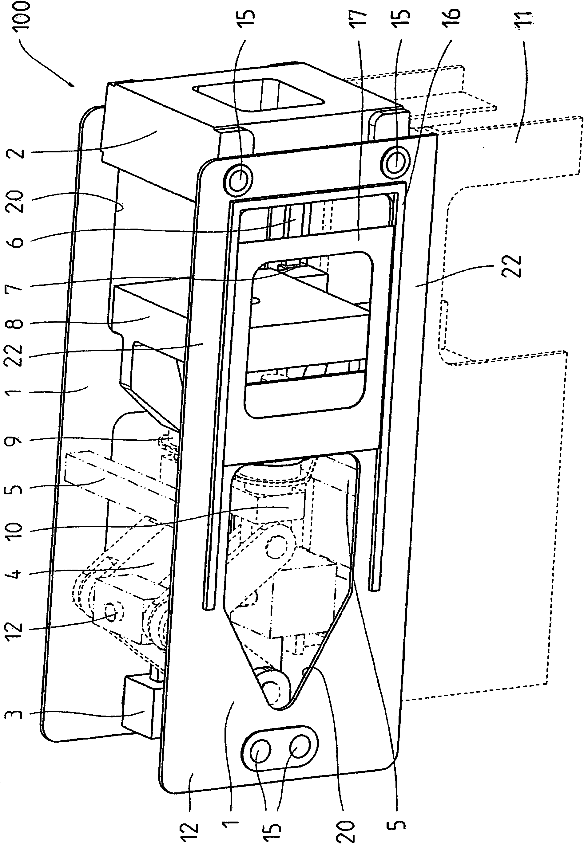
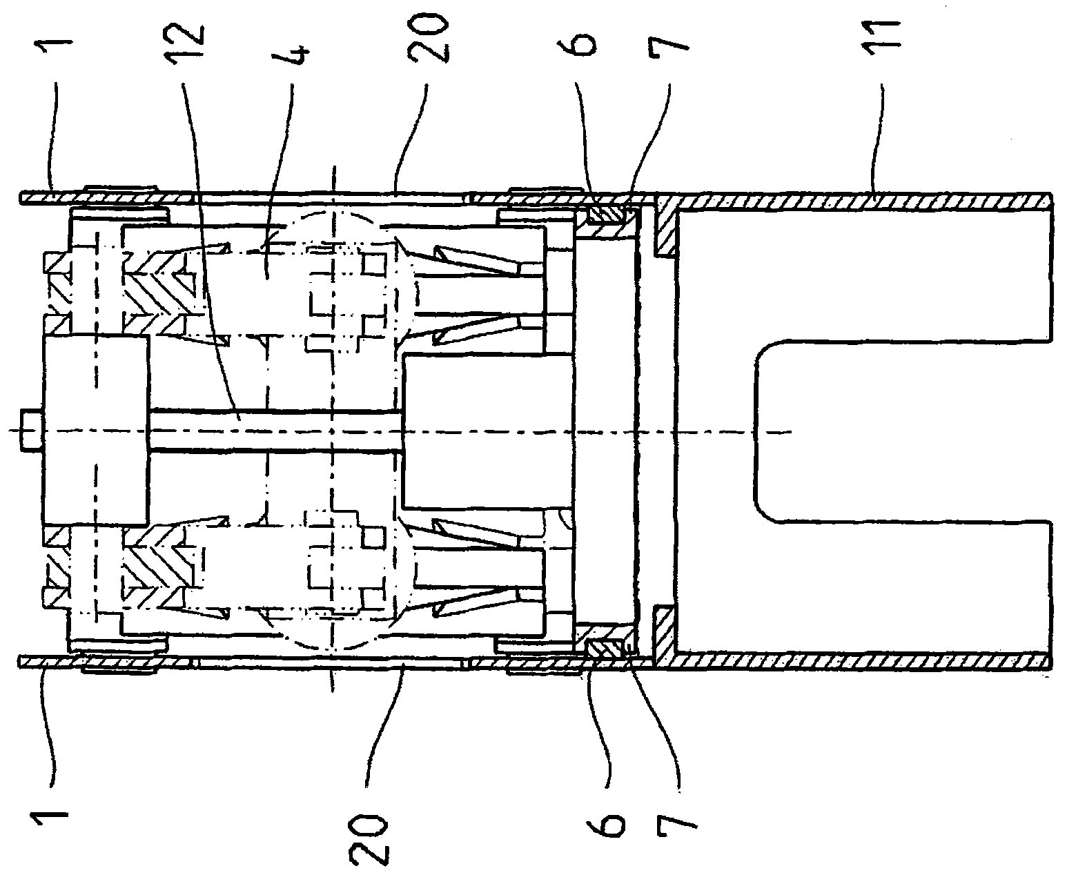
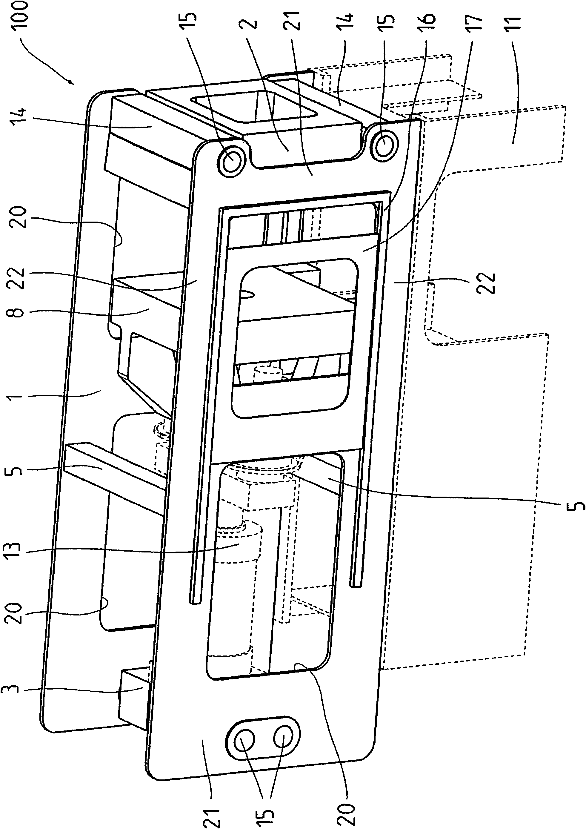
[0035] injection molding machine in figure 1The closure unit 100 shown in FIG. 1 shows a front and a rear side wall 1 . The side walls 1 have the shape of upstanding plates and extend substantially over the entire length of the closure unit 100 . The side walls 1 are connected directly to a fixed mold clamping plate 2 and to a receiving bracket 3 for the closing mechanism 4 by means of pins 15 and further reinforcing brackets 5 . The closing mechanism 4 is a toggle closing mechanism with a drive 12 . The reinforcing brackets 5 serve as beams (supports) and together with the side walls 1 form the bracket of the invention for the closing unit which receives or transmits the entire force flow when the closing force is built up. The stand stands with the side walls 1 on the frame 11 of the closing unit 100 . These side walls 1 simultaneously serve as protective linings.

[0036] Guide rails 6 are fastened on the inside of the side walls 1 in the longitudinal direction of the m...


PUM


Abstract

The invention relates to an injection molding machine (110) having a closing unit (100) and an injection unit (101), wherein a frame having side walls (1) and traverses (5, 14) connecting the side walls (1) to one another absorbs the forces of the closing unit (100) as a closed system and / or wherein a frame having side walls (1) and traverses (5, 14) connecting the side walls (1) to one another absorbs the forces of the injection unit (101) as a closed system, wherein the side walls (1) form a substantially complete protective covering for the closing unit (100) and / or the injection unit (101).

Description

technical field [0001] The invention relates to an injection unit for an injection molding machine. Background technique [0002] Injection molding machines are known from the prior art in various configurations and generally have four cylindrical transverse arms for transmitting the force generated by the closing mechanism. The disadvantage here is that the transverse arms are arranged in the space between the clamping plates of the tool and thus limit the size of the tool. [0003] Furthermore, cross-armless injection molding machines are known, in which the closing mechanism and the mold clamping plate are arranged in a C-shaped machine frame. Such a cross-armless injection molding machine is described, for example, in AT 391 293 B. The disadvantage of such cross-armless injection molding machines, namely the ease of access to the space between the mold clamping plates, is that the machine frame of such injection molding machines has to be constructed in an expensive so...

Claims


Application Information

Patent Timeline
Patent Type & Authority Patents(China)
IPC IPC(8): B29C45/46B29C45/17
CPCB29C2045/1797B30B15/04B29C45/1761
Inventor H·拉贝D·伊赛尔V·弗里茨拉J·迈耶A·芬斯特雷尔S·弗伦茨
Owner HAITIAN PLASTICS MACHINERY GRP
Why Eureka
Try Eureka