
Umbrella type variable gauge inflate tool for expansion tube
An umbrella-type and variable technology, applied in wellbore/well components, earth-moving drilling, etc., can solve complex problems and achieve the effects of easy processing and manufacturing, increasing expansion volume, and small expansion force
- Summary
- Abstract
- Description
- Claims
- Application Information
AI Technical Summary
Problems solved by technology
Method used
Image

Examples
Embodiment Construction
[0012] The present invention will be further described now in conjunction with the accompanying drawings of the description.
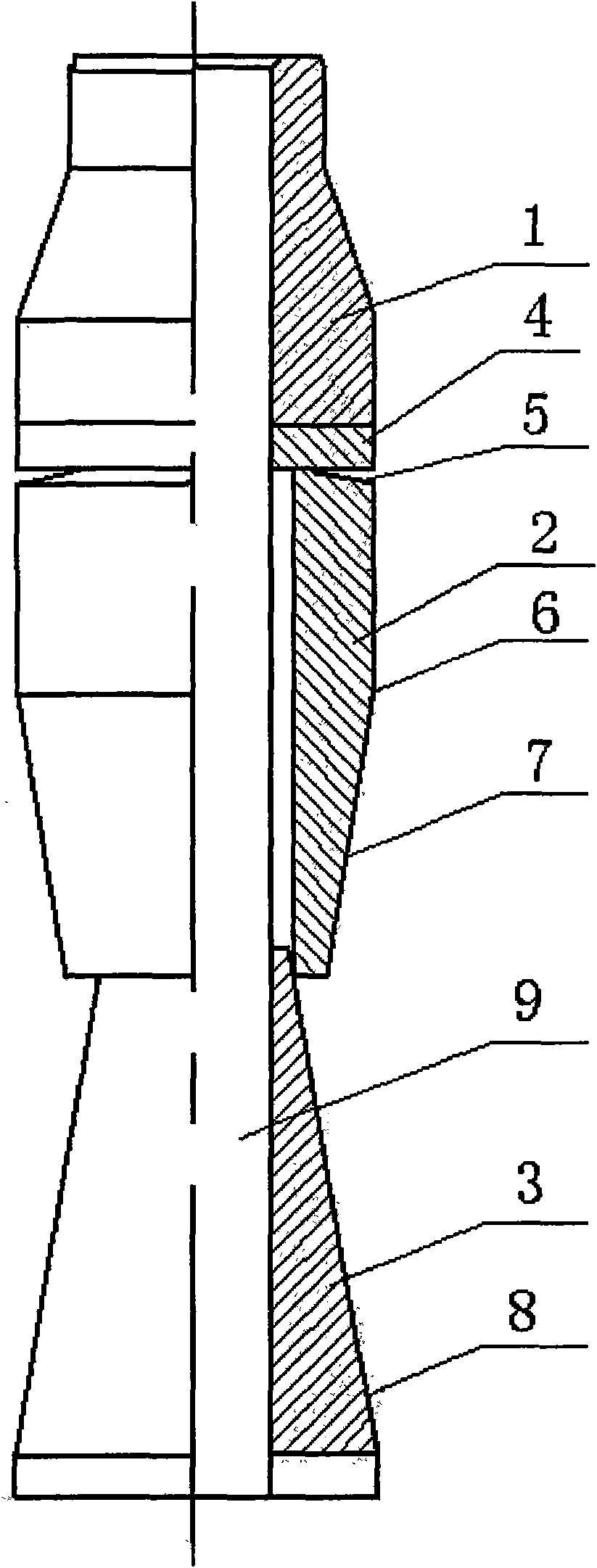
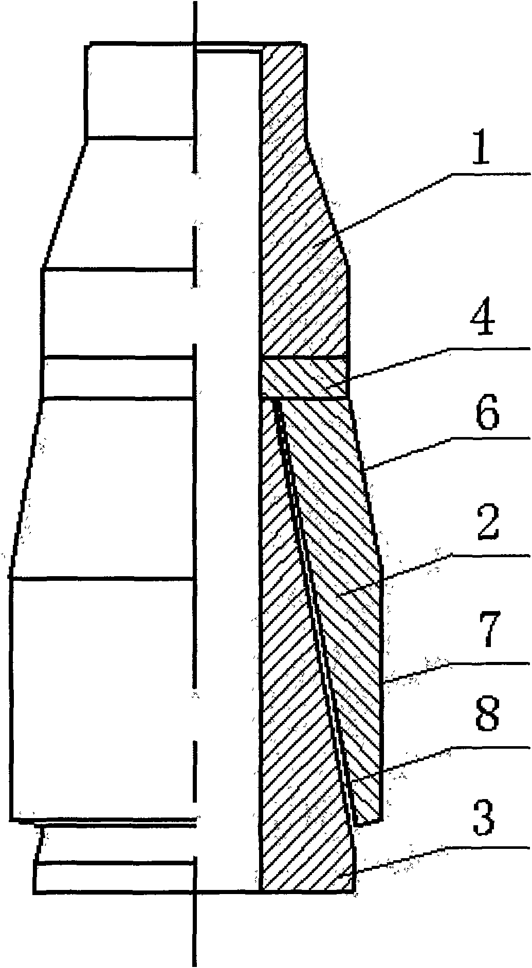
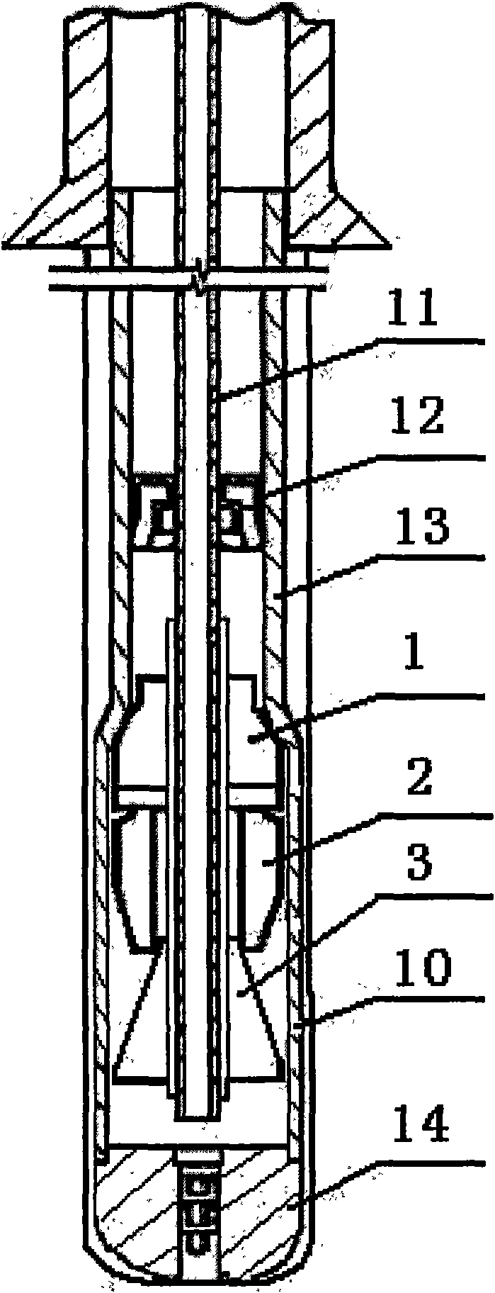
[0013] Umbrella-type variable-diameter expansion tools for expansion pipes, such as figure 1 As shown, it includes two parts, the fixed cone 1 and the variable diameter cone. The fixed cone 1 and the variable diameter cone are independent components. The fixed cone 1 is a cone through-hole structure with a narrow top and a wide bottom. 2. The expansion top cone 3 and the bottom plate 4 are composed of a number of expansion cones 2 installed on the reducing cone, which are combined on the bottom plate through T-shaped grooves, etc., and the reducing cones 2 can move within an appropriate range under the action of external force , the expansion top cone 3 is a conical structure with a narrow top and a wide bottom, and the top end is located in the central through hole 9 of the expansion cone sheet 2 .
[0014] Such as figure 1 , figure 2 As shown, th...
PUM
 Abstract
Description
Claims
Application Information