Lens shifter and projection type image display device with the same

A technology of moving the lens and moving the base, which is applied to projection devices, printing devices, optics, etc., can solve the problems of increased sliding resistance, larger driving force, and inability to move smoothly, and achieves the goal of reducing sliding resistance and moving smoothly. Effect

Active Publication Date: 2011-05-04
SANYO ELECTRIC CO LTD
View PDF5 Cites 3 Cited by
  • Summary
  • Abstract
  • Description
  • Claims
  • Application Information

AI Technical Summary

Problems solved by technology

However, when the tooth width becomes larger, the sliding resistance on the contact surface of the teeth becomes larger and the driving force becomes larger, so smooth movement may not be possible
In particular, in the case of the conventional example described above, when the horizontally movable base member 20 is moved horizontally, the rack gear 53 to which a moving force in the vertical direction is applied keeps the state of meshing with the gear portion 52g and simultaneously moves to the left and right. The mechanism that moves in the direction, so the increase of the sliding resistance on the rack transmission member 53 becomes a problem

Method used


Image

  • Lens shifter and projection type image display device with the same
  • Lens shifter and projection type image display device with the same
  • Lens shifter and projection type image display device with the same

Examples


Embodiment approach 1

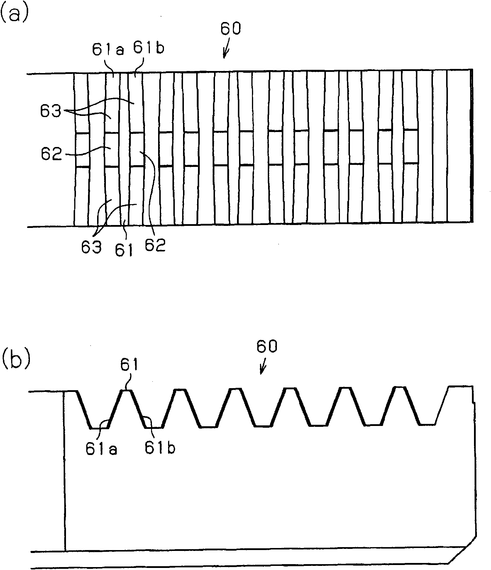
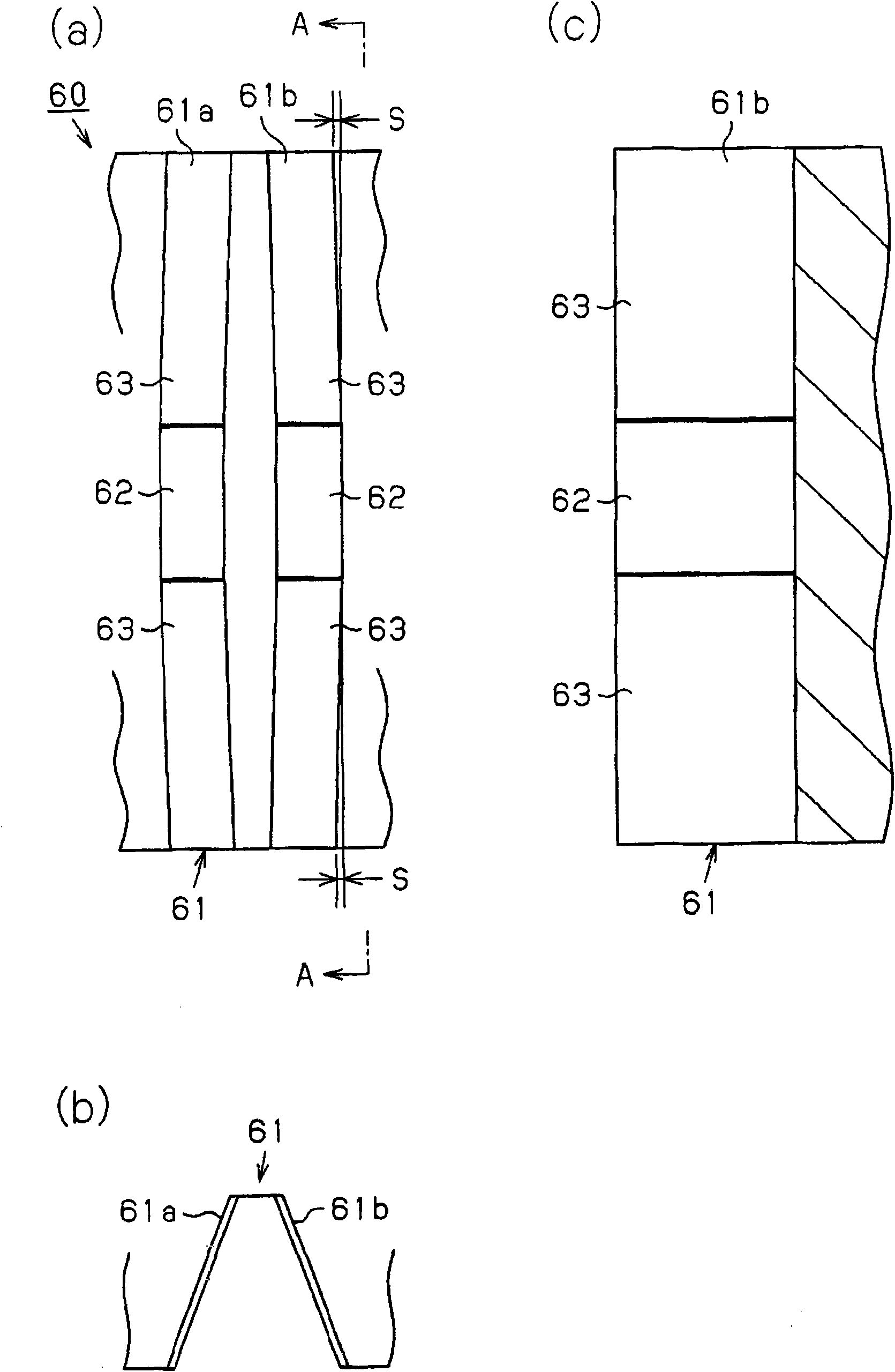
[0054] In the lens moving device according to Embodiment 1 of the present invention, the rack gears 43 and 53 are changed to figure 1 and figure 2 The device of the rack transmission member 60 shown, other structures and Figure 6 ~ Figure 8 The structure shown is the same. Therefore, in the following description, for the structure other than the rack transmission member 60, as having Figure 6 ~ Figure 8 The components of the structure shown are described.

[0055] That is, the lens moving device of the present embodiment includes a fixed base member 1 , a movable base member 2 , and a drive mechanism unit 4 . In addition, the movable base member 2 includes: a horizontally movable base member 20 configured to be movable in the left-right direction relative to the fixed base member 1; The vertically movable base member 30.

[0056] Further, the driving mechanism unit 4 includes a horizontal driving mechanism unit 40 for moving the horizontally movable base member 20 in th...

Embodiment approach 2

[0069] Next, based on Figure 3 ~ Figure 5 , and the lens moving device according to Embodiment 2 will be described. Also, in the following description, the image 3 The perspective view of is a perspective view viewed from the front side, and the up, down, left, and right directions are defined based on this figure.

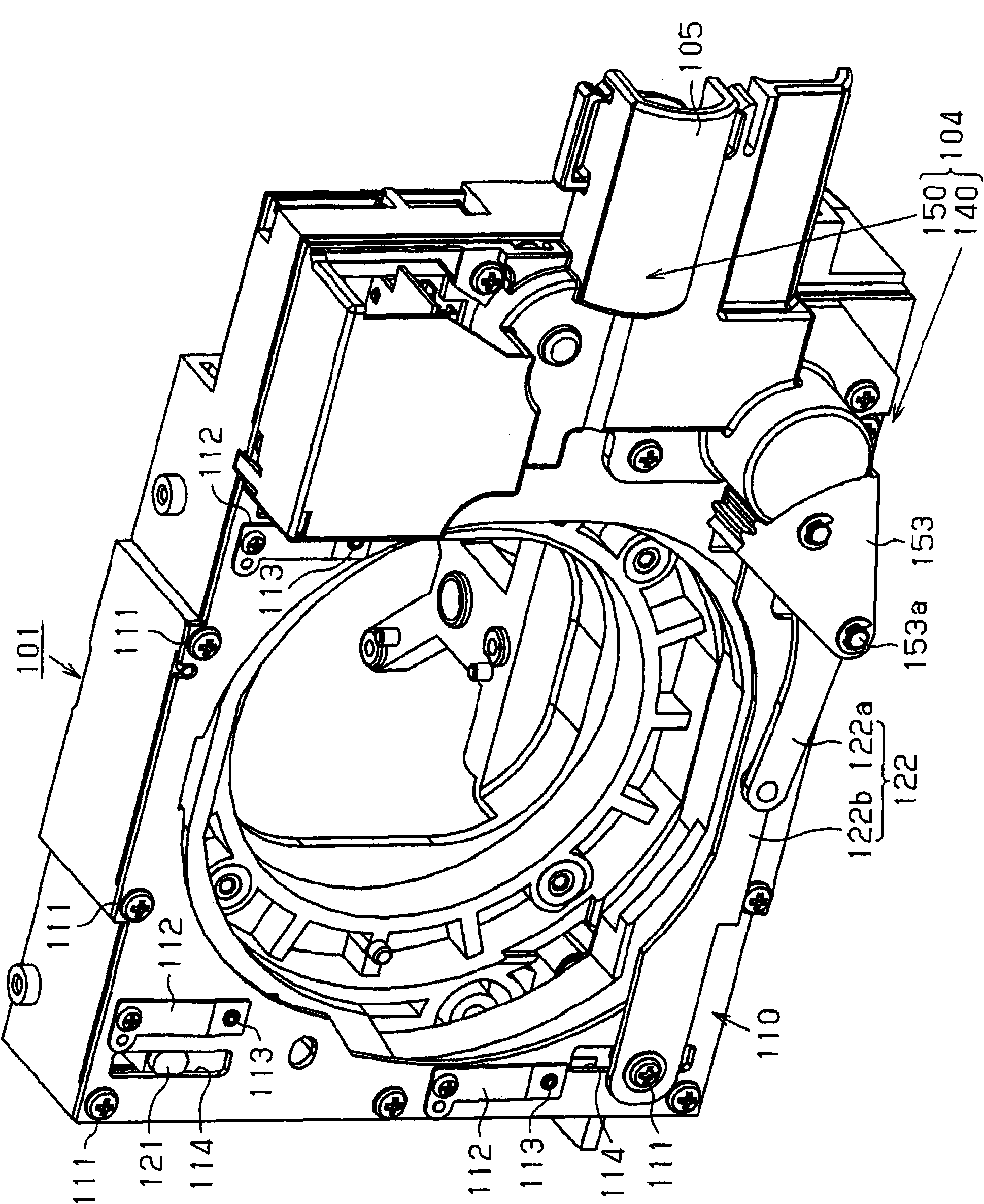
[0070] This lens moving device is a lens moving device in a three-panel liquid crystal projection type image display device similarly to the previous embodiments. and, if Figure 4 As shown, the lens moving device includes: a fixed base member 110 fixed to the unit frame 101; ; The drive mechanism section 104 that moves the movable base member 102 relative to the fixed base member 110 . Furthermore, a projection lens is mounted on the movable base member 102 .

[0071] Such as image 3 As shown, the fixed base member 110 is mounted from the front by a plurality of small screws 111 to the unit frame 101 fixed to a frame portion formed by upstanding walls ar...


PUM


Abstract

The present invention provides a lens shifter in which a rack transmission member is used as a power transfer mechanism for transmitting a moving force in a horizontal direction or a vertical direction, and a projection type image display device with the lens shifter, which improves strength of the rack transmission member and restrains increase of sliding resistance. The lens shifter of the invention comprises the following components: a fixed base component which is fixed to a body frame; a movable base component which is provided with a projection lens and is configured to move in a vertical direction, a left-and-right direction or both directions relatively to the fixed base component; and a driving mechanism part which causes the movement of the movable base component relatively to the fixed base component. The driving mechanism part comprises the following components: a driving part which is used for performing driving operation to the driving mechanism part; a gear mechanism part which transfers a force applied by the driving part; and a rack transmission member (60) which receives the force from the gear mechanism part. In the rack transmission member (60), a contact surface (62) which transfers power is only formed on a part in a tooth direction of the tooth surfaces (61a,61b).

Description

technical field [0001] The present invention relates to a lens moving device of an optical mechanism for moving the position of a projection lens in a horizontal and / or vertical direction. Background technique [0002] Generally, in a projector that projects an image on a screen, it is necessary to project a projected image to a predetermined position on the screen. Therefore, a lens moving device is used that adjusts the horizontal position and / or vertical position of a projected image by moving the position of the projection lens in the horizontal direction and / or vertical direction. [0003] As such a projection-type video display device, for example, a projection-type video display device using a lens moving device described in Patent Document 1 is known. based on Figure 6 ~ Figure 8 The projection type image display device will be described. It should be noted that in the following description, the Figure 6 The perspective view of is a perspective view viewed from ...

Claims


Application Information

Patent Timeline
Patent Type & Authority Applications(China)
IPC IPC(8): G03B5/04G03B21/14G03B21/00
CPCG03B5/04G03B21/147
Inventor 吉村太一
Owner SANYO ELECTRIC CO LTD
Why Eureka
Try Eureka