Chip resistor conductor layer drying equipment and using method thereof

A technology for chip resistors and drying equipment, which is used in the cleaning method of tools, resistors, resistors manufacturing, etc., to avoid dust blockage, reduce friction, and smooth moving operations.

Inactive Publication Date: 2021-10-22
安徽省富捷电子科技有限公司
View PDF1 Cites 0 Cited by
  • Summary
  • Abstract
  • Description
  • Claims
  • Application Information

AI Technical Summary

Problems solved by technology

[0005] The purpose of the present invention is to provide a chip resistor conductor layer drying equipment and its use method, which can solve the existing problems

Method used


Image

  • Chip resistor conductor layer drying equipment and using method thereof
  • Chip resistor conductor layer drying equipment and using method thereof
  • Chip resistor conductor layer drying equipment and using method thereof

Examples


Embodiment 1

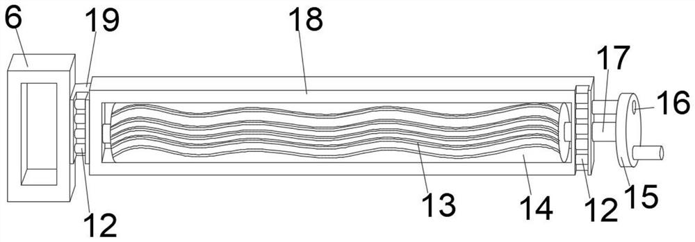
[0032]The cross-section of the fixed brush head 13 is a wave-shaped structure, and the outer surface of one end of the movable sliding frame 18 is fixedly equipped with a sliding card holder 19, and the inner side of the sliding card holder 19 and the other end of the moving sliding frame 18 are all movably installed with several groups of moving parts. The card wheel 12 utilizes the fixed brush head 13 of wave-shaped structure to clean up the accumulated dust in the exhaust hood 5 and the fixed side box 8 through the fixed brush head 13 when the movable slide frame 18 moves, and simultaneously utilizes the mobile card The setting of the wheel 12 can facilitate the movement of the sliding frame 18 for push-pull operation.

[0033] The moving slide frame 18 and the rolling brush rod 14 are movably connected by the docking rotating rod 17, and the outer surface of one end of the docking rotating rod 17 is fixedly equipped with a rotating disc 15, and the inner side of the rotatin...

Embodiment 2

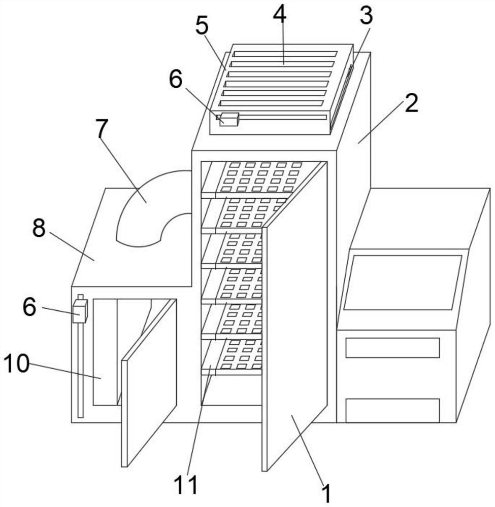
[0035] The inside of the fixed side box 8 is fixedly equipped with a dryer 10, and the inside of the fixed side box 8 and the exhaust hood 5 are provided with a dust discharge groove 3 and an air flow hole 4. Through the setting of the dust discharge groove 3, the fixed side box can 8 and the exhaust hood 5 complete the dust removal operation, the dust in the fixed side box 8 and the exhaust hood 5 is discharged, and the drying machine 10 cooperates with the connecting pipe 7 to perform drying and heating operations on the inside of the drying cabinet 2.

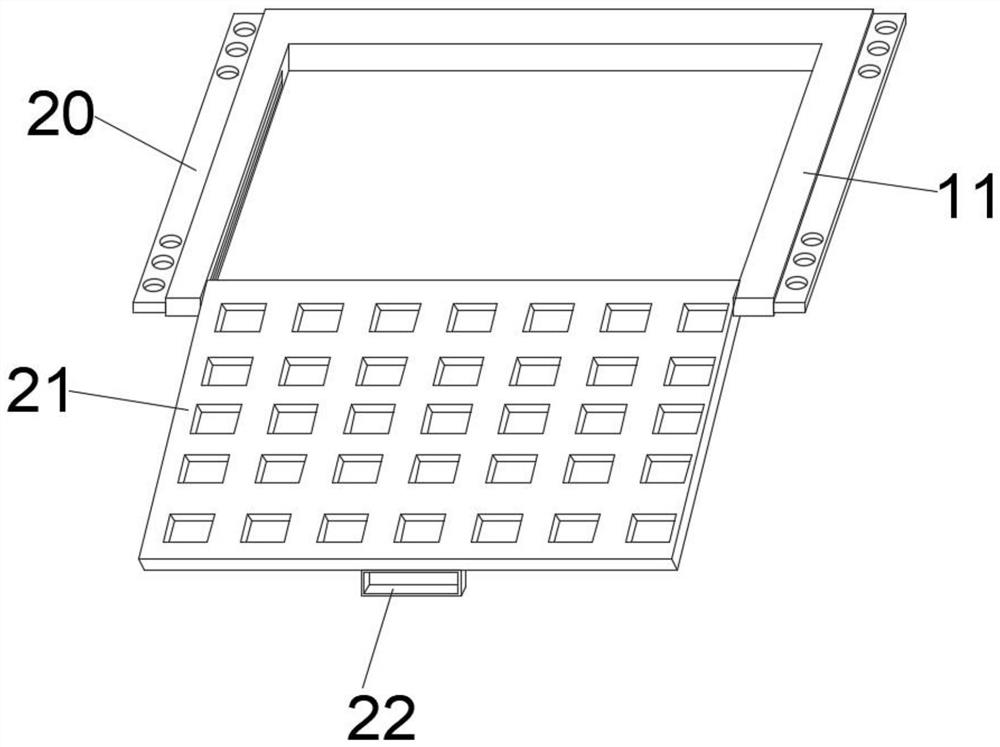
[0036] Two sets of push-pull grooves 9 are provided on the inner side of the fixed clamp 11, and two sets of positioning clamps 20 are fixedly installed on the outer surface of the side of the fixed clamp 11, and the positioning clamps 20 are passed between the fixed clamp 11 and the drying cabinet 2. Fixed connection, the upper part of the material setting plate 21 is provided with a rectangular notch, and the bottom of the ...


PUM


Abstract

The invention discloses chip resistor conductor layer drying equipment and a using method thereof. The chip resistor conductor layer drying equipment comprises a drying cabinet and a fixed side box. The fixed side box is fixedly installed on the outer surface of one side of the drying cabinet, a communicating pipe is arranged between the fixed side box and the drying cabinet, and an exhaust hood is fixedly installed on the outer surface of the upper end of the drying cabinet. Push-pull buckles are movably installed on the outer surfaces of the side edges of the exhaust hood and the fixed side box, a movable sliding frame is fixedly installed at one end of each push-pull buckle, the movable sliding frames are movably installed on the inner sides of the exhaust hood and the fixed side box, and a rolling brush rod is movably installed in the middle of the inner side of each movable sliding frame. The movement of the movable sliding frames is matched with the rolling brush rods in a fixed state to conduct dust removal operation on the interior of the equipment, and meanwhile the movement of the movable sliding frames is matched with the rolling brush rods in a rotating state to discharge cleaned dust from a dust discharging groove, so that dust removal operation on the interior of the equipment is completed under the condition that the equipment is not disassembled, and the phenomenon that the equipment is blocked due to accumulated dust is avoided.

Description

technical field [0001] The invention belongs to the technical field of resistance conductor processing, and more specifically relates to a chip resistance conductor layer drying equipment and a use method thereof. Background technique [0002] The chip resistor conductor layer drying equipment is used in the production and processing of chip resistors to dry and process chip resistors covered with conductor layers, so that the conductor layer is cured on the surface of chip resistors, reducing the The time required for the conductor layer to cure. [0003] Patent No. CN202591083U discloses a drying device for resistive paint, which includes a drying box. There are support seats at both ends of the drying box, and there are swivel seats on the support seats. On the rotating shaft, each supporting frame is composed of two discs connected by a connecting shaft, and the wall at one end of the drying box is provided with a motor whose output shaft extends into the drying box and...

Claims


Application Information

Patent Timeline
Patent Type & Authority Applications(China)
IPC IPC(8): H01C17/00B08B1/00B08B1/04
CPCH01C17/006H01C17/00B08B1/002B08B1/04
Inventor 周海生陈庆良魏效振
Owner 安徽省富捷电子科技有限公司
Why Eureka
Try Eureka