Light path structure and method for detecting large-dynamic range liquid turbidity

A technology with a large dynamic range and detection optical path, which is used in transmittance measurement, scattering characteristic measurement and other directions to achieve the effect of accurate detection, elimination of interference, and improved accuracy

Inactive Publication Date: 2011-07-20
ANHUI INST OF OPTICS & FINE MECHANICS - CHINESE ACAD OF SCI
View PDF5 Cites 36 Cited by
  • Summary
  • Abstract
  • Description
  • Claims
  • Application Information

AI Technical Summary

Problems solved by technology

[0003] On the basis of the scattering method and the transmission method, the present invention provides a unique liquid turbidity detection optical path structure and a matching detection method, which realizes the combined measurement of the transmission preference and the scattering signal, and overcomes the single method in terms of accuracy and range. At the same time, the modulation and demodulation technology is used to effectively eliminate the interference of background light, greatly improving the accuracy of measurement, so as to realize the accurate detection of water turbidity in a large range of changes, and ensure that the turbidity meter designed by this method It has good detection ability and can meet the needs of accurate detection of water turbidity in a large dynamic range

Method used


Image

  • Light path structure and method for detecting large-dynamic range liquid turbidity
  • Light path structure and method for detecting large-dynamic range liquid turbidity
  • Light path structure and method for detecting large-dynamic range liquid turbidity

Examples


Embodiment Construction

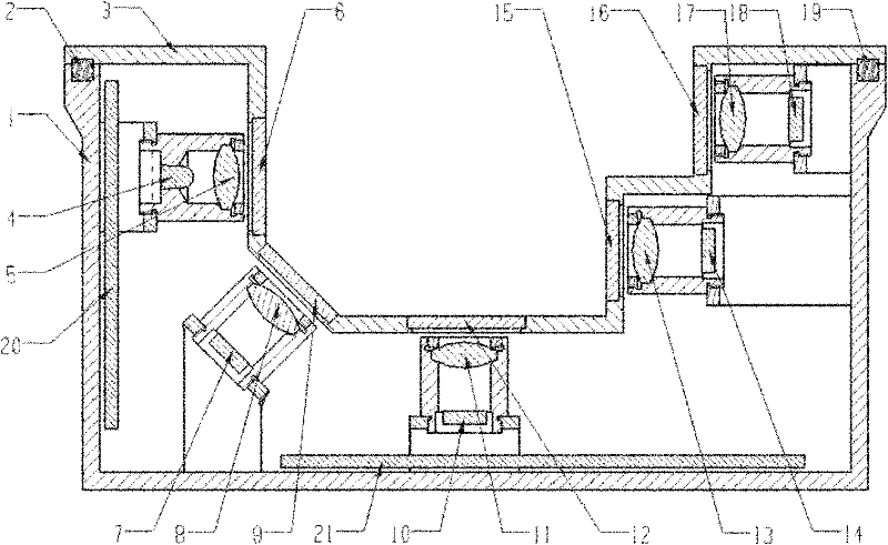
[0032] Such as figure 1As shown, the large dynamic range liquid turbidity detection optical path structure includes a housing 1, which is made of stainless steel, and is used to place a light source, a detector and a corresponding circuit in it; Cover plate 3, the right side wall of the concave cavity is in a stepped structure, and light windows are installed on the left side wall of the concave cavity, the bottom of the concave cavity, the left corner of the concave cavity, the upper part of the right side wall, and the lower part of the right side wall on the cover plate 6, 9, 12, 15, 16, convex lens 5, detection light source (infrared LED, Siemens BPW37, center wavelength 860nm) 4, the bottom of the cavity, the left corner of the cavity are installed in the housing behind the light window 6 on the left side wall Convex lenses 8, 11, 13, 17 and photodetectors (photocells) 7, 10, 14, 18 are respectively installed at the housing at the place, the upper part of the right side w...


PUM


Abstract

The invention discloses a light path structure and a method for detecting large-dynamic range liquid turbidity. In the light path structure, an infrared emission light path, a first scattered light path, a second scattered light path, a long vessel transmission light path and a short vessel transmission light path are arranged in a groove-shaped concave cavity respectively; after being subjected to beam expanding by a convex lens in the front, light emitted from a detecting light source is transmitted in liquid in the concave cavity and is received by light detectors respectively, and an electrical signal outputted by each light detector is inputted to an amplification demodulator circuit to be converted into a direct-current voltage signal for calculating liquid turbidity; and the detecting light source realizes pulse modulation by the demodulator circuit. By the structure and the method, the requirement of the accurate detection of the turbidity of various water bodies with different concentrations is met fully, so the structure can be used for detecting water turbidity quickly on line by environmental monitoring departments and also can be used for performing long-term continuous detection on the water turbidity of fixed monitoring points by being arranged on a buoy or an automatic monitoring station, and has the excellent market prospect.

Description

technical field [0001] The invention belongs to the field of environmental monitoring technology and analysis, in particular to a liquid turbidity detection optical path and a detection method. Background technique [0002] In order to improve the water purification technology and production management level, it is very important to realize the online detection of water quality. Turbidity detection is an important parameter of water quality detection. In the past operation of water quality detection, turbidity detection was manually measured by colorimetry, light ratio and other methods. The randomness and dispersion of the obtained data are relatively large. Now online continuous measurement is used. , and convert the data into electrical signals immediately, which can ensure the stability and accuracy of detection. In the international standard (IS07027-1984), the transmission method and the scattering method are two standard measurement methods for nephelometer design. ...

Claims


Application Information

Patent Timeline
Patent Type & Authority Applications(China)
IPC IPC(8): G01N21/59G01N21/51
Inventor 张玉钧张恺殷高方王志刚石朝毅肖雪段静波王欢博于绍慧刘文清
Owner ANHUI INST OF OPTICS & FINE MECHANICS - CHINESE ACAD OF SCI
Why Eureka
Try Eureka