Multiple-input multiple-output (MIMO) multicasting beamforming method

A beamforming method and beamforming vector technology, applied in diversity/multi-antenna systems, space transmit diversity, etc., can solve the problems of large amount of calculation, poor performance, and inability to effectively apply to actual communication systems, etc., and achieve high channel capacity , reduced computational complexity, and significant performance advantages

Inactive Publication Date: 2011-07-20
UNIV OF SCI & TECH OF CHINA
View PDF3 Cites 10 Cited by
  • Summary
  • Abstract
  • Description
  • Claims
  • Application Information

AI Technical Summary

Problems solved by technology

[0005] The purpose of the present invention is to propose a multiple-input multiple-output (MIMO) multicast beamforming method, to improve the existing SDR randomization method in the process of obtaining beamforming vectors with large computational load and poor performance, Problems that cannot be effectively applied to practical communication systems

Method used


Image

  • Multiple-input multiple-output (MIMO) multicasting beamforming method
  • Multiple-input multiple-output (MIMO) multicasting beamforming method
  • Multiple-input multiple-output (MIMO) multicasting beamforming method

Examples


Embodiment 1

[0018] Embodiment 1: MIMO multicast beamforming method with 8 transmitting antennas and 16 user scenarios

[0019] In this embodiment, the base station is configured with 8 transmitting antennas, a single multicast user group, and the group includes 16 user scenarios as an example to introduce the specific implementation of the present invention.

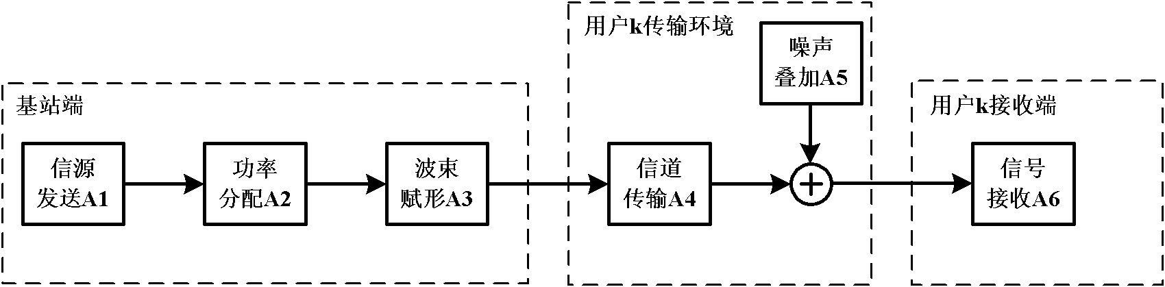
[0020] figure 1 A schematic diagram of the MIMO downlink signal processing process for user k is given. In the base station-side source sending step A1, let the source signal be x and satisfy x∈£ M×1 After the power allocation step A2, the power P is allocated to the user k, and the beamforming vector w provided in the beamforming step A3 completes the base station MIMO transmission beamforming, then the base station transmission signal can be expressed as The signal is physically transmitted through the user k transmission environment: Step A4 is transmitted through the channel, and the transmitted signal is transmitted through the ch...

Embodiment 2

[0043] Embodiment 2: MIMO multicast beamforming method with 16 transmitting antennas and variable number of users

[0044] In this embodiment, a scenario where the base station is configured with 16 transmitting antennas, a single multicast user group, and the group contains a variable number of users is taken as an example to introduce the specific implementation of the present invention.

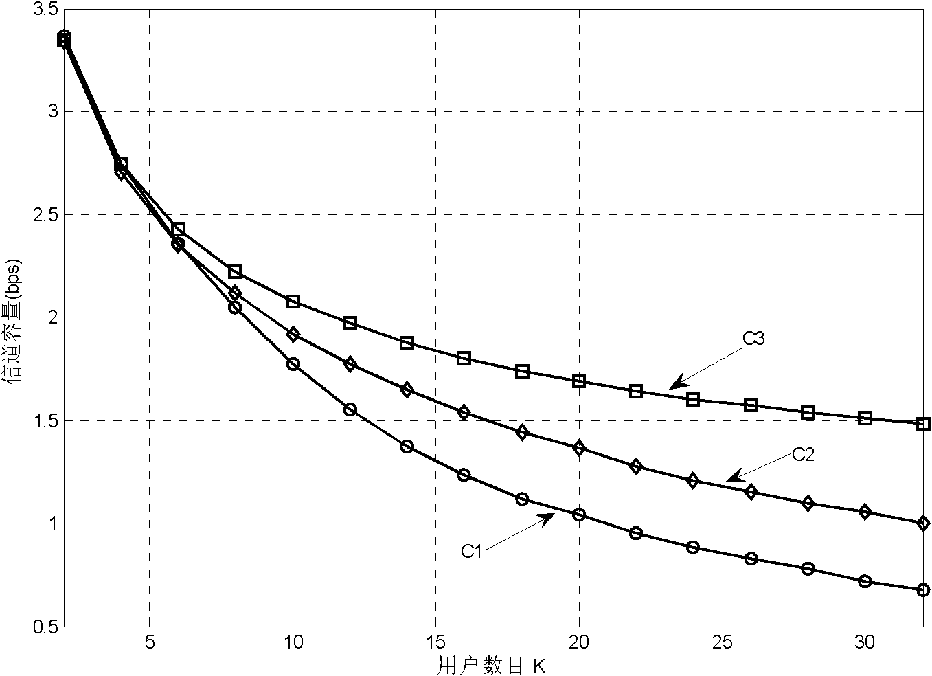
[0045] Suppose that the number of transmit antenna configurations at the base station is M = 16, the transmit power P = 1, and the number of receive antenna configurations for each user in the MIMO multicast user group is N k =1, the number of users in the group K is variable, and the range of change is K∈[2,32]. Using Rayleigh flat fading channel, the noise variance of each user sub-channel is And it is assumed that the transmitting end accurately knows the MIMO channel state information (CSI) corresponding to each user.

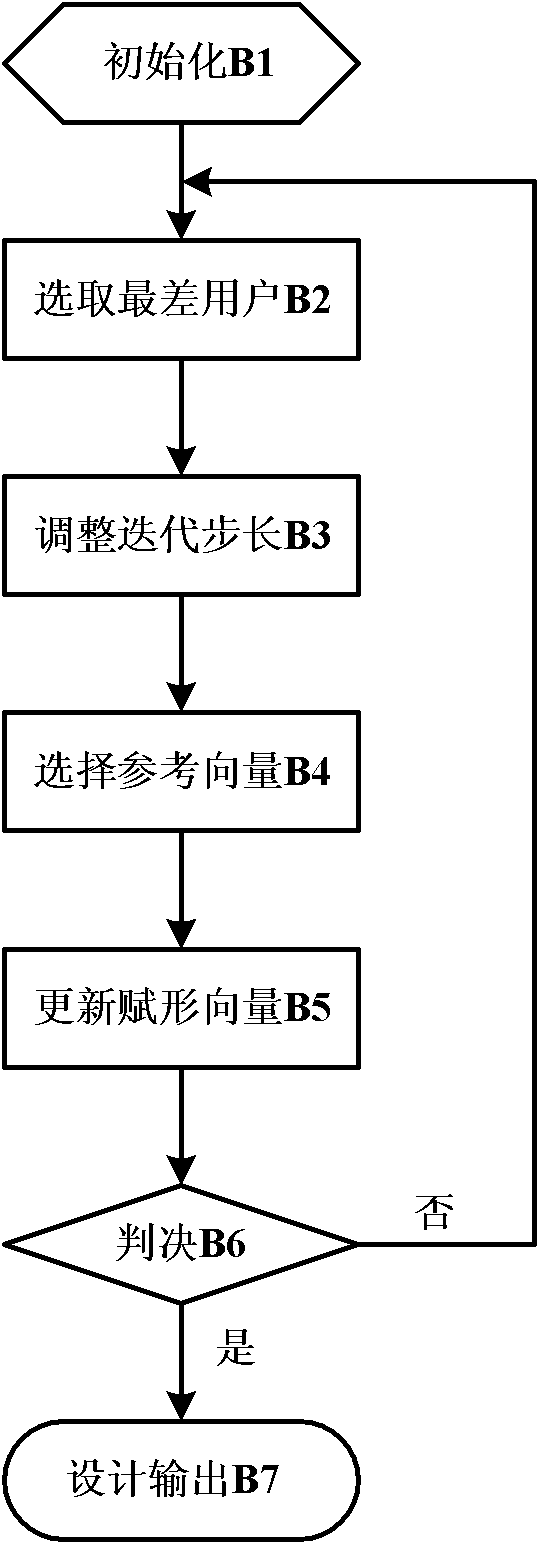
[0046] For each determined number of users K in the group, the method of...


PUM


Abstract

The invention discloses a multiple-input multiple-output (MIMO) multicasting beamforming method, which is characterized by comprising the following steps of: adopting iterative search with adjustable step length; decomposing a channel matrix corresponding to a user with the worst signal to noise ratio in a group by utilizing singular value decomposition (SVD) in the process of each step of iteration, and acquiring a maximum right singular vector of the channel matrix; and approaching a beamforming vector to the direction of the maximum right singular vector gradually. Compared with the conventional single data rate (SDR) randomization method, the method has the advantages that: the beamforming vector acquired by the method can increase channel capacity effectively and have lower operation complexity simultaneously. Moreover, as the number of transmitting antennae configured in a base station end is increased and the number of the users in the group is increased, the method provided by the invention has the more obvious performance advantages and is applicable for implementation in new generation MIMO broadband wireless and mobile communication systems of 802.11n, time division high speed packet access + (TD-HSPA+) and time division long term evolution (TD-LTE).

Description

Technical field [0001] The present invention belongs to the field of multiple-input multiple-output (MIMO) broadband wireless and mobile communication technologies, and specifically relates to a beamforming method for single-user group MIMO multicast downlink, and is suitable for new technologies such as 802.11n, TD-HSPA+ and TD-LTE. A generation of broadband wireless and mobile communication systems. Background technique [0002] Different from the traditional omnidirectional antenna or fixed-beam antenna transmission mode, how to effectively design the beamforming vector in the MIMO multicast service to improve the utilization of wireless spectrum resources has attracted widespread attention in the industry. In particular, designing and searching for effective MIMO multicast transmission strategies to ensure the fairness of multicast users has always been the main research content in related fields. The MIMO multicast service can be understood as the coverage of a base station...

Claims


Application Information

Patent Timeline
IPC IPC(8): H04B7/06
Inventor 许小东杜柏生戴旭初
Owner UNIV OF SCI & TECH OF CHINA
Why Eureka
Try Eureka