Multisegment picture reconstruction for cardio ct pictures

An image reconstruction and computer technology, which is applied in the directions of instruments, computing, and image enhancement for radiological diagnosis, and can solve problems such as displacement and image motion blur.

Active Publication Date: 2011-11-09
SIEMENS HEALTHCARE GMBH
View PDF4 Cites 4 Cited by
  • Summary
  • Abstract
  • Description
  • Claims
  • Application Information

AI Technical Summary

Problems solved by technology

[0004] A disadvantage of this generally known calculation method is that, when the examination object is in motion, or at least partially in motion, motion blur occurs in the image, because during the time of the scanning process for the data required for an image, Displacement of the inspection object or part of the inspection object may occur, so that the underlying data forming the image does not reflect the same state in all spaces of the inspection object

Method used


Image

  • Multisegment picture reconstruction for cardio ct pictures
  • Multisegment picture reconstruction for cardio ct pictures
  • Multisegment picture reconstruction for cardio ct pictures

Examples


Embodiment Construction

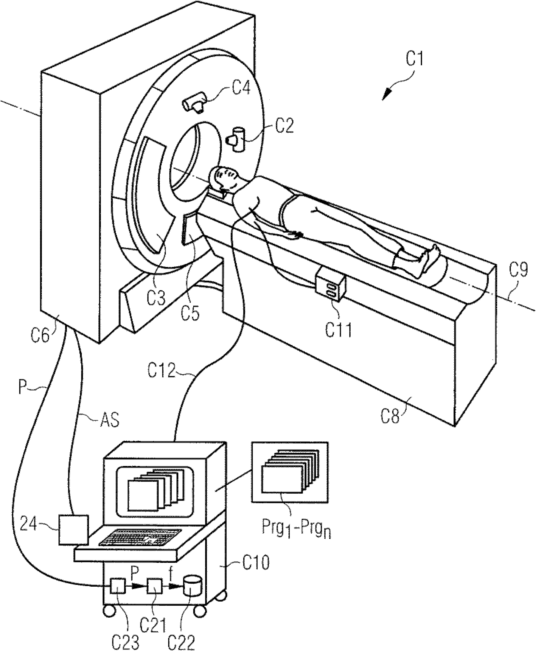
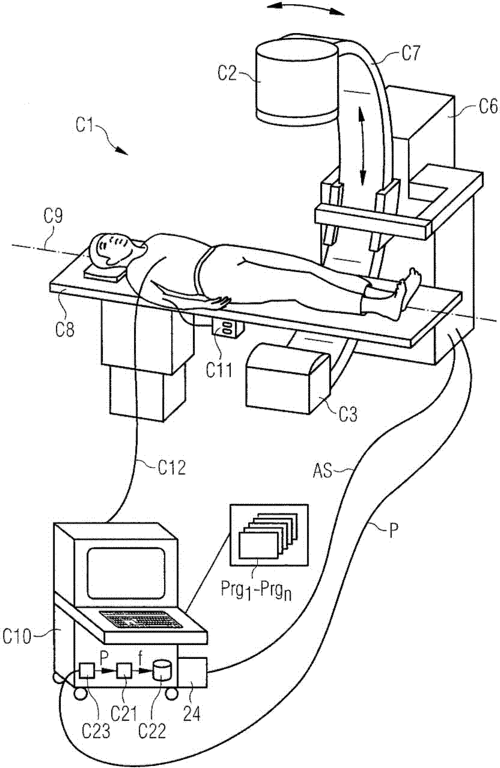
[0029] figure 1 Firstly, a first computed tomography system C1 with an image reconstruction device C21 is shown schematically. This is a so-called third-generation CT system, although the invention is not limited to this CT system. In the gantry housing C6 there is a closed gantry, not shown, on which a first x-ray tube C2 with an opposite detector C3 is arranged. Optionally, in the CT system shown here, a second x-ray tube C4 with an opposite detector C5 is provided, so that a higher temporal resolution can be achieved by additional available emitter / detector combinations, Alternatively, “dual-energy” examinations can also be carried out using different X-energy spectra in the emitter / detector system.

[0030]Furthermore, the CT system C1 has a patient table C8 on which the patient can be pushed along the system axis C9 (also referred to as the z-axis) into the measurement field during the examination, wherein a purely circular scan can also be performed The scan itself is...


PUM


Abstract

A method for reconstructing picture data (PIC) of a cyclically-moving object from measurement data is disclosed, with the measurement data being detected beforehand for a relative rotational movement between a radiation source (C2, C4) of a computed tomography system (C1) and the object under examination during a plurality of movement cycles of the object under examination. A first picture (PIC MEAN) and a second picture (PIC SEG) are determined from the measurement data, with measurement data of different movement cycles being combined for reconstruction of the second picture (PIC SEG) into a measurement dataset to be used as the basis for the picture reconstruction. Difference information (DIF) is computed by comparing the first picture (PIC MEAN) with the second picture (PIC SEG). Using the difference information (DIF), a result picture (PIC) is computed from the first picture (PIC MEAN) and the second picture (PIC SEG).

Description

technical field [0001] The invention relates to a method for reconstructing image data of a periodically moving examination object from measurement data, wherein a relative rotation between a radiation source of a computed tomography system and the examination object is performed beforehand during a plurality of motion cycles of the examination object Collect measurement data while in motion. Background technique [0002] Methods of scanning an examination object using a CT system are generally known. In this case, for example, circular scanning, sequential circular scanning with advance or helical scanning is used. Other kinds of scans that are not based on circular motion are also possible, eg scans with linear segments. Absorption data of the examination object are recorded from different recording angles by means of at least one x-ray source and at least one opposed detector, and the absorption data or projections thus collected are calculated as cross-sectional images...

Claims


Application Information

Patent Timeline
IPC IPC(8): A61B6/03G06T11/00A61B5/352
CPCA61B6/503G06T2207/10081A61B6/5264G06T11/005G06T2207/30004G06T2211/412A61B6/507G06T5/003G06T5/50G06T5/73
Inventor 托马斯·阿尔曼丁格伯恩哈德·施米特
Owner SIEMENS HEALTHCARE GMBH
Why Eureka
Try Eureka