Supercharge Your Innovation With Domain-Expert AI Agents!

High-power LED (light emitting diode) light emitting device package structure

A light-emitting device packaging and high-power technology, applied in the direction of electric solid-state devices, semiconductor devices, electrical components, etc., can solve the problems of difficult control of consistency, loss of light efficiency, complex process, etc., to overcome poor consistency and simplify the process and the effect of the production process

Inactive Publication Date: 2013-07-03
IRICO
View PDF6 Cites 0 Cited by
  • Summary
  • Abstract
  • Description
  • Claims
  • Application Information

AI Technical Summary

Problems solved by technology

However, the loss of light efficiency of LED light-emitting devices is serious during the assembly process from chip to LED package and then to optical devices. A wide range of applications, it is very important to obtain a simple and easy packaging method

Method used


Image

  • High-power LED (light emitting diode) light emitting device package structure
  • High-power LED (light emitting diode) light emitting device package structure

Examples


Embodiment 1

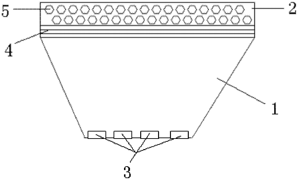
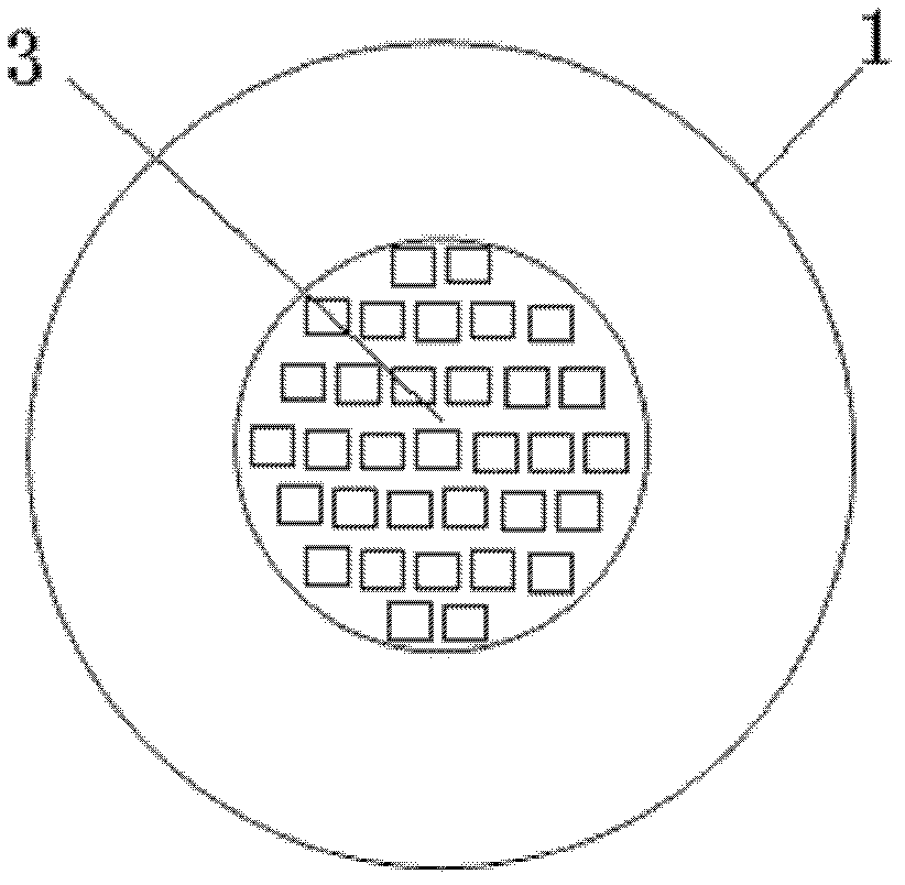
[0018] Embodiment 1: The packaging structure of a high-power LED light-emitting device includes a blue-light chip module, a reflective cup, and fluorescent glass. The blue light chip module is obtained by integrating 33 blue light LED chips. The reflective cup can optimize the light path effect. The yellow fluorescent substance is evenly distributed inside the fluorescent glass. Through this packaging method, white light can be realized, and the distance between the fluorescent glass and the blue light chip module can be adjusted through threads. A comprehensive optical test of the light-emitting device through an integrating sphere shows that its color temperature is 3000K-8000K.

Embodiment 2

[0019] Embodiment 2: The packaging structure of the high-power LED light-emitting device includes a blue-light chip module, a reflective cup, and fluorescent glass. The blue light chip module is obtained by integrating one blue light LED chip. The reflective cup can optimize the light path effect, and the yellow and red fluorescent substances are evenly distributed inside the fluorescent glass. Through this packaging method, white light with high color rendering can be realized, and the fluorescent light can be adjusted through threads The distance between the glass and the blue light chip module, the comprehensive optical test of the light emitting device through the integrating sphere shows that its color temperature is 3000K-8000K.

Embodiment 3

[0020] Embodiment 3: The packaging structure of the high-power LED light-emitting device includes a blue-light chip module, a reflective cup, and fluorescent glass. The blue light chip module is obtained by integrating 55 blue light LED chips. The reflective cup can optimize the light path effect. The green and red fluorescent substances are evenly distributed inside the fluorescent glass. Through this packaging method, the white light of the three primary colors can be realized. The fluorescent glass and the fluorescent glass can be adjusted through threads. The distance between the blue light chip modules, the comprehensive optical test of the light emitting device through the integrating sphere shows that its color temperature is 3000K-8000K.


PUM


Abstract

The invention aims to provide a high-power LED (light emitting diode) light emitting device package structure which is simple and easy to implement. The structure comprises a reflection cup and fluorescent glass which is packaged at the top part of the reflection cup; and an LED chip module is packaged in the bottom part of the reflection cup. The invention has the beneficial effect that the high-power LED light emitting device package structure adopts a light emitting mode which combines the LED chip module and the fluorescent glass; according to the invention, the process flow that LED chips do not need to be packaged into LEDs independently and then the LEDs are assembled into a light emitting device is omitted, therefore the problem of poor consistence caused by LED chips are packagedsingly can be overcome, and the process and production flow of the light emitting device in the package process are simplified, and the packaging structure is simple and easy to implement.

Description

technical field [0001] The invention relates to a package structure of an LED light-emitting device, in particular to a package structure of a high-power LED light-emitting device. Background technique [0002] LED (Light Emitting Diode) is a semiconductor light-emitting device, which has attracted much attention due to its advantages of high light efficiency, energy saving, green environmental protection, high safety, long life, fast response, and low operating cost. Against this backdrop, energy-saving and environmentally friendly LED products are expected to become the next generation of light sources and have huge market prospects. [0003] At present, LED is widely used in landscape lighting, signal lights, automobile industry, backlight module, daily lighting and other fields, and its advantages are gradually emerging. However, the loss of light efficiency of LED light-emitting devices is serious during the assembly process from chip to LED package and then to optical...

Claims


Application Information

Patent Timeline
Patent Type & Authority Patents(China)
IPC IPC(8): H01L33/50H01L25/075
Inventor 赵金鑫
Owner IRICO
Features
  • R&D
  • Intellectual Property
  • Life Sciences
  • Materials
  • Tech Scout
  • Unparalleled Data Quality
  • Higher Quality Content
  • 60% Fewer Hallucinations
Learn More