

A new structure of stapler base and support
A stapler, a new type of technology, applied in the direction of metal processing equipment, etc., can solve the problems of complex manufacturing process, low material utilization rate, and many manufacturing processes, and achieve the effect of fewer manufacturing processes, improved utilization rate, and increased productivity
Inactive Publication Date: 2011-12-21
宋平德
View PDF0 Cites 0 Cited by
- Summary
- Abstract
- Description
- Claims
- Application Information
AI Technical Summary
Problems solved by technology
[0003] The purpose of the present invention is to: provide a structure of a novel stapler base and a support, to overcome the defects in the structure of the existing stapler base and support, resulting in many manufacturing processes, complex manufacturing processes, and poor material quality. Lower Utilization, Higher Cost Defects
Method used
View moreImage
Smart ImageViewing Examples

Examples
Embodiment Construction
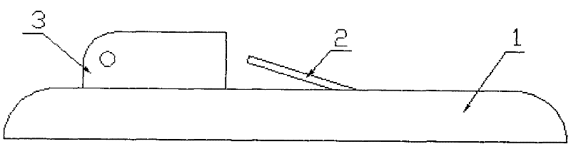
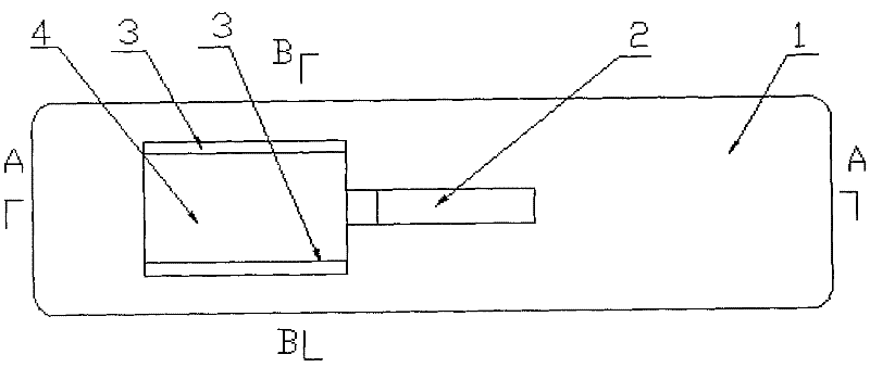
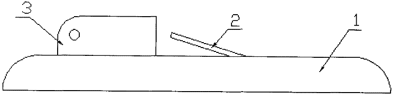
[0009] The base (1) is manufactured by adopting the steel plate cold stamping process, and the square hole (4) is pointed out at the midline of one end of the base (1); at the same time as the square hole is made, the material of the square hole is transformed into a symmetrical shape through the flanging process The two brackets (3) of the bracket (3), at the midline of the base (1) at one end of the bracket (3), use a cold cutting method to separate a part of the material from the base (1) and press the separated part upward to form a return spring (2).
Login to View More PUM
 Abstract
The invention discloses a novel stapler base and bracket structure, which adopts a steel plate cold stamping process to integrate the base, bracket, and return spring into one structure. Specifically: use the cold stamping process of steel plate to manufacture the base, and point out the square hole at the midline of one end of the base; while making the square hole, through the flanging process, two symmetrical brackets are made at the same time, and the base at one end of the bracket At the midline, a part of the material is cut and separated from the base part by cold cutting method, and the separated part is pressed upward to form a return spring.
Description
technical field [0001] The invention relates to a structure of a stapler base and a bracket, in particular to a novel stapler base and a bracket structure, belonging to the technical field of stationery. Background technique [0002] At present, it is known that the base, the bracket and the return spring of the stapler are separate structures, and after being manufactured independently, they are then riveted and installed and fixed on the base. The structure of this independent structure has many manufacturing processes, The defects of complex manufacturing process, low material utilization rate and high cost. Contents of the invention [0003] The purpose of the present invention is to: provide a structure of a novel stapler base and a support, to overcome the defects in the structure of the existing stapler base and support, resulting in many manufacturing processes, complex manufacturing processes, and poor material quality. Lower utilization, higher cost defects. ...
Claims
Login to View More Application Information
Patent Timeline
 Patent Type & AuthorityApplications(China)
IPC IPC(8): B21D53/00B21D35/00
Inventor宋平德
Owner宋平德