A permanent magnet liquid-cooled retarder with multi-head structure

A retarder, permanent magnet fluid technology, applied in the direction of permanent magnet clutch/brake, etc., can solve the problems of retarder work failure, poor work reliability, easy to throw out magnets, etc., to achieve high safety performance, light rotor weight , the effect of small moment of inertia

Inactive Publication Date: 2016-01-20
BEIJING UNIV OF TECH
View PDF4 Cites 0 Cited by
  • Summary
  • Abstract
  • Description
  • Claims
  • Application Information

AI Technical Summary

Problems solved by technology

[0004] The permanent magnet retarder disclosed in the invention patent (Patent No. ZL200910237634.8) named "Permanent Magnet Sliding Permanent Magnet Liquid Cooling Retarder" is composed of a number of permanent magnets and magnet cages, and the permanent magnets are evenly distributed On the magnet holder, the magnet will rotate with the transmission shaft at high speed, and the magnet holder is connected to the cylinder through the bearing, so that the magnet holder can slide axially while rotating with the transmission shaft. , it is subjected to a large centrifugal force, and the magnet is easy to be thrown out and easily broken, causing the retarder to malfunction
At the same time, these structures make the retarder complex in structure and poor in assembly, resulting in high cost and poor work reliability

Method used


Image

  • A permanent magnet liquid-cooled retarder with multi-head structure
  • A permanent magnet liquid-cooled retarder with multi-head structure
  • A permanent magnet liquid-cooled retarder with multi-head structure

Examples


Embodiment Construction

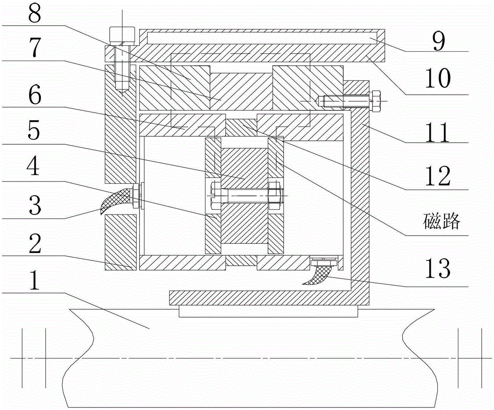
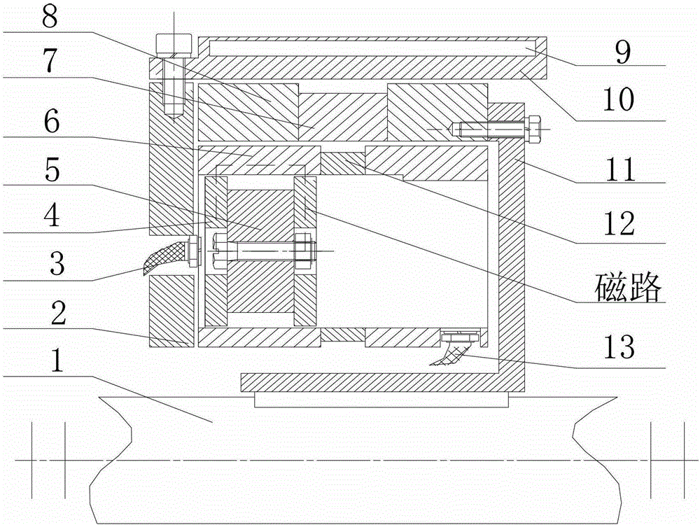
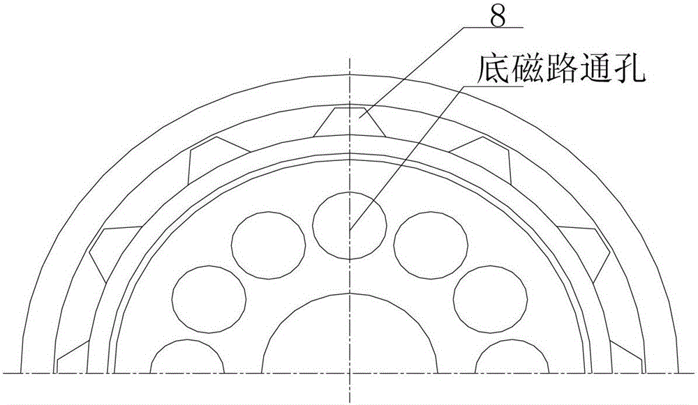
[0016] The specific embodiments of the present invention will be further described below with reference to the accompanying drawings. like figure 1 and figure 2 As shown, one end of the rotor arm 11 in the embodiment of the present invention is connected to the transmission shaft 1 through a key, and the other end of the rotor arm 11 is connected to the retarder rotor (including the two rotor salient poles 8 and the rotor non-magnetic conductive ring 7) through screws. A rotating part is formed; a number of permanent magnets 5 are evenly distributed in the through hole of the bottom magnetic circuit 6, the permanent magnet 5 can move axially in the through hole, and the cylindrical permanent magnet 5 and the magnetic conductive blocks 4 at both ends are connected by bolts. The connection can move along the axial direction with the permanent magnet 5 in the through hole of the bottom magnetic circuit 6; the upper air inlet 3 is installed on the left circular end face of the ...


PUM


Abstract

A permanent magnetic liquid cooling retarder with a multi-magnetic head structure relates to auxiliary braking system for an automobile. The retarder comprises a rotor, a stator, permanent magnets, a magnetic block, a bottom magnetic circuit, an upper air inlet and a lower air inlet, wherein the plurality of permanent magnets are uniformly distributed in a through hole of the bottom magnetic circuit in the circumferential direction and are pneumatically controlled to axially slide in the stator; the rotor is connected with a transmission shaft via a rotor arm; a 1 mm gap is reserved between the inner circumference of the stator and the outer circumference of the rotor; the inner circumference of the rotor is separated from the outer circumference of the bottom magnetic circuit by a 1 mm gap; a cooling water channel connected with an automobile circular heat radiation water tank is arranged in the stator. The retarder has a simple structure, is high in working reliability, the relative axial position and the working amount of the permanent magnets in the bottom magnetic circuit are regulated, thereby changing output force moment and further achieving braking force moment grouping regulation of the permanent magnetic retarder; and the permanent magnets axially slide in the through hole of the bottom magnetic circuit, do not rotate, and are free from centrifugal force and high in safety.

Description

technical field [0001] The invention relates to a permanent magnet retarder, which uses a permanent magnet as a magnetic source to generate an eddy current braking torque by cutting a magnetic field line on a rotating and non-contact metal arc surface, in particular to a permanent magnet as an eddy current braking The magnetic source adopts the retarder cooled by circulating water. Background technique [0002] The car retarder is an auxiliary braking device for automobiles. Most of the existing retarders use eddy current and hydraulic retarders. The permanent magnet retarder overcomes the shortcomings of the existing hydraulic and eddy current retarders, and adopts a non-contact method to apply the braking torque to the vehicle. The driveshaft brakes, thereby slowing the car. The permanent magnet retarder forms a magnetic field through its own permanent magnet, which plays a retarding role, so there is almost no power consumption. [0003] The biggest features of permane...

Claims


Application Information

Patent Timeline
Patent Type & Authority Patents(China)
IPC IPC(8): H02K49/10
Inventor 李德胜尹汪雷张凯张龙喜
Owner BEIJING UNIV OF TECH
Why Eureka
Try Eureka