Sealing parts

A technology for sealing parts and cylinders, which is applied to the sealing device of the engine, engine components, machines/engines, etc., can solve the problems of difficult assembly, increased assembly resistance, thermal deformation, vibration and wear offset, etc. Cost, reduction in the number of parts, and the effect of preventing poor assembly

Inactive Publication Date: 2015-08-12
ROKI CO LTD
View PDF8 Cites 0 Cited by
  • Summary
  • Abstract
  • Description
  • Claims
  • Application Information

AI Technical Summary

Problems solved by technology

[0013] However, according to the mounting method of the sealing member described in Patent Document 1, since the threaded portion is formed of an elastic material such as rubber, and the threaded portion has two functions of holding the sealing member and sealing function, when the threaded surface is enlarged in order to exert the sealing function, When the contact force is high, the assembly resistance increases when the seal is screwed together, making assembly difficult.
[0014] In addition, according to the mounting method of the sealing member described in Patent Document 2, since the supporting member of the sealing member is connected and fixed by bolts or the like, there is a problem that the number of parts increases, the weight and the number of mounting steps increase, and it is very difficult to attach and detach the sealing member.
[0015] Furthermore, according to the mounting method of the sealing member described in Patent Document 3, since the sealing member and the cylinder head cover are assembled by concave-convex engagement, there is a possibility of misalignment due to thermal deformation, vibration, abrasion, and the like. There is a problem of impairing the sealing function

Method used


Image

  • Sealing parts
  • Sealing parts
  • Sealing parts

Examples


no. 1 approach

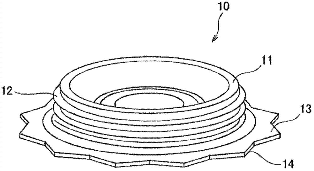
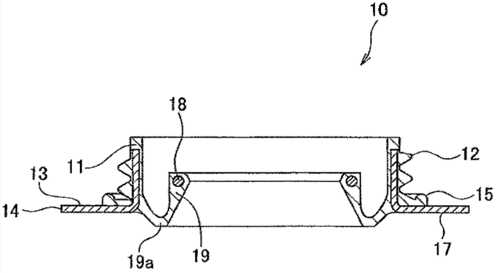
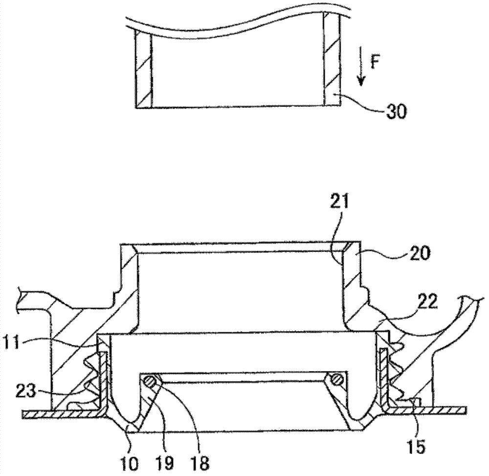
[0061] figure 1 It is a perspective view for explaining the outline|summary of the sealing member of 1st Embodiment, figure 2 is a longitudinal sectional view of the sealing member of the first embodiment, image 3 It is a longitudinal sectional view for explaining the mounting state of the sealing member of the first embodiment, Figure 4 is a longitudinal sectional view illustrating a modified example of the sealing member of the first embodiment, Figure 5 It is a longitudinal sectional view for explaining another modified example of the sealing member of the first embodiment.

[0062] Such as figure 1 As shown, the sealing member 10 of this embodiment includes a cylindrical portion 11 formed in a hollow cylindrical shape and having a helical thread groove 12 formed on the outer peripheral surface, and a radial direction extending from one end of the axial direction of the cylindrical portion 11 to the cylindrical portion 11. Extended installation action part 14. The ...


PUM


Abstract

The invention provides a sealing part, which is advantageous in that, without addition of number of components and assembly procedures, a sealing part can be reliably fixed on a cylinder cover via simple structure, and the sealing part and the cylinder cover can be reliably sealed. The sealing part is provided with: a cylindrical part extending in the axis direction of a spark plug installing hole and provided with a screw-shaped screw thread groove at the outer periphery, and an installing acting part provided with an opposite surface opposite to the cylinder cover and formed at one end of the axis direction of the cylindrical part, the spark plug installing hole is provided with an internal screw thread groove in a screw thread joint with the screw thread groove at the internal circumferential surface, and a step part protruding to the direction of the internal circumference in a mode opposite to the other end of the axis direction of the cylindrical part, surface sealing devices in a press joint in the direction of the axis with respect to the cylinder cover at the other end of the direction of the axis of the cylindrical part and any part or both parts of the opposite surface are provided.

Description

technical field [0001] The present invention relates to a sealing member, and more particularly to a structure of the sealing member interposed between a spark plug mounting hole formed in a cylinder head cover of an internal combustion engine and a mounting member through which the spark plug is inserted. Background technique [0002] Conventionally, a head cover made of synthetic resin is attached to the upper portion of an internal combustion engine for the purpose of weight reduction and design improvement. A spark plug is attached to the upper part of the internal combustion engine, and the spark plug is inserted through a mounting member such as a cylindrical spark plug tube, and further inserted into a spark plug mounting hole formed in the cylinder head cover. [0003] A sealing member is interposed between the spark plug tube and the spark plug mounting hole for the purpose of liquid-tightly sealing the gap between the spark plug mounting hole and the spark plug tub...

Claims


Application Information

Patent Timeline
Patent Type & Authority Patents(China)
IPC IPC(8): F02F11/00F02F7/00
Inventor 佐藤泰辅柳泽统铃木兵升
Owner ROKI CO LTD
Why Eureka
Try Eureka