Transmission with electromechanical unit and oil circuit

A transmission, electromechanical technology, applied to components with teeth, mechanical equipment, transmission parts, etc., can solve problems such as user obstruction

Inactive Publication Date: 2016-07-13
GETRAG FORD TRANSMISSIONS GMBH
View PDF7 Cites 0 Cited by
  • Summary
  • Abstract
  • Description
  • Claims
  • Application Information

AI Technical Summary

Problems solved by technology

During this time the ability to drive the path is re-established, but this can be perceived by the user as a hindrance

Method used


Image

  • Transmission with electromechanical unit and oil circuit
  • Transmission with electromechanical unit and oil circuit
  • Transmission with electromechanical unit and oil circuit

Examples


Embodiment Construction

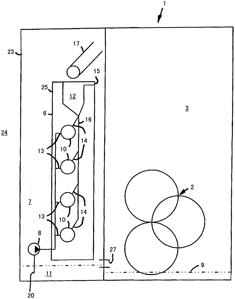
[0025] figure 1 A transmission is schematically represented in . The transmission 1 comprises a transmission unit 2 with intermeshing gearwheels, which is arranged in a transmission chamber 3 . The gear wheels of the transmission unit 2 are immersed in oil 9 which collects in an oil sump in the lower center of the transmission chamber 3 . In addition there is a figure 1 The clutch unit 4, not shown, is located in a clutch chamber 5. And oil can also collect below in the clutch chamber 5 .

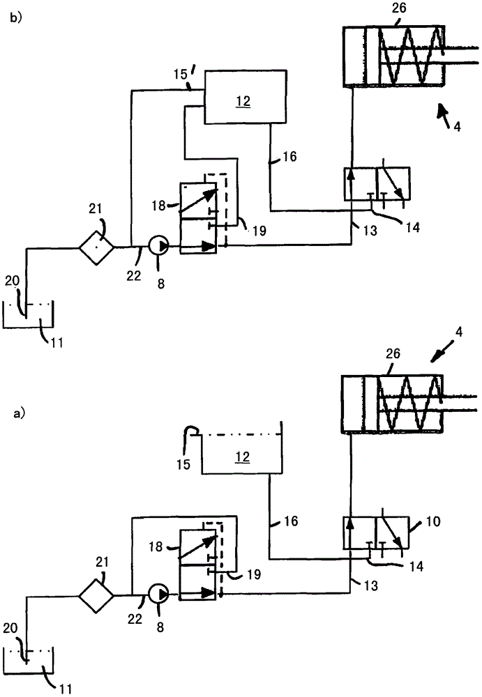
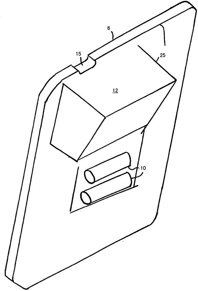
[0026] An electromechanical unit 6 is arranged in a suction chamber 7 . The electromechanical unit here comprises a plurality of clutch valves 10 , in this example four clutch valves. However, a different number of clutch valves is also possible. Oil can also collect below the suction chamber 7 . An oil pump 8 is provided here, which sucks oil 9 from the suction chamber 7 . Oil 9 can flow through a channel 27 between the individual chambers above a certain minimum oil level.

[002...


PUM


Abstract

The invention relates to a transmission (1), especially an automatic shift transmission for automobiles, comprising: a transmission unit (2); a clutch unit (4); an electromechanical unit (6); The circuit comprises an oil pump (8) which draws oil (9) from a first reservoir (11) and from which oil (9) can be supplied to the various units, the electromechanical unit (6) comprising at least one clutch valve (10 ), the clutch valve is set to control the clutch unit (4), at least one clutch valve (10) includes a pressure port (13) for at least indirectly connecting the clutch valve (10) to the oil pump (8) and for at least indirectly The clutch valve is connected to the drain connection of the second oil reservoir, which is formed separately from the first oil reservoir, and the second oil reservoir has an overflow port, which is arranged on the electromechanical unit above all clutch valves.

Description

technical field [0001] The present invention relates to transmissions, and more particularly to automatic shift transmissions for automobiles. Background technique [0002] EP1637757B1 gives such a transmission and a method for lubricating and cooling it. A transmission chamber with transmission components disposed therein, a clutch chamber with clutch components disposed therein, and a hydraulic control section are described therein. To control and cool the clutch components an oil pump draws oil from a suction chamber and pumps it into the clutch chamber. There is a functional connection between the suction chamber and the transmission chamber, so that oil can be discharged from the suction chamber into the transmission chamber. Furthermore, there is a functional connection between the clutch chamber and the transmission chamber, so that oil can be discharged from the transmission chamber into the clutch chamber. [0003] From EP 1065401 A2 a clutch control device is kn...

Claims


Application Information

Patent Timeline
Patent Type & Authority Patents(China)
IPC IPC(8): F16H57/04
CPCF16H57/045F16H57/0445F16H57/0446F16H57/0494F16H61/0009F16H61/0021F16H2061/0037
Inventor O·S·珀茨R·默尔曼
Owner GETRAG FORD TRANSMISSIONS GMBH
Why Eureka
Try Eureka