Laser cutting head for laser machining equipment

A laser cutting head and laser processing technology, applied in laser welding equipment, metal processing equipment, welding equipment, etc., can solve problems such as unsuitable low-end laser engraving equipment, inability to complete focal length, product processing quality problems, etc., to achieve automatic Focus and defocus, improve the efficiency of laser processing and the effect of product processing quality

Active Publication Date: 2012-08-29
江苏大族粤铭激光科技有限公司
View PDF12 Cites 9 Cited by
  • Summary
  • Abstract
  • Description
  • Claims
  • Application Information

AI Technical Summary

Problems solved by technology

Manual focus has the following disadvantages: 1. Low processing efficiency; 2. Manual adjustment errors are likely to cause product processing quality problems; 3. In some occasions that require automatic switching between focus and defocus, manual adjustment cannot complete the accurate switch of focal length
Although some high-end laser cutting models have auto-focus function, the quality of the mobilization module is too heavy and the cost is too high, so it is not suitable for low-end laser engraving equipment that needs to run at high speed

Method used


Image

  • Laser cutting head for laser machining equipment
  • Laser cutting head for laser machining equipment
  • Laser cutting head for laser machining equipment

Examples


Embodiment Construction

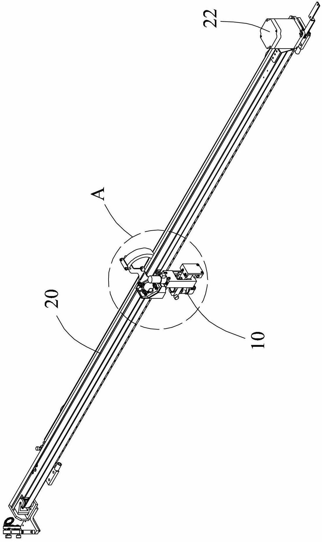
[0019] Such as Figure 1 to Figure 4 Shown is a preferred embodiment of the laser cutting head 10 used in laser processing equipment according to the present invention.

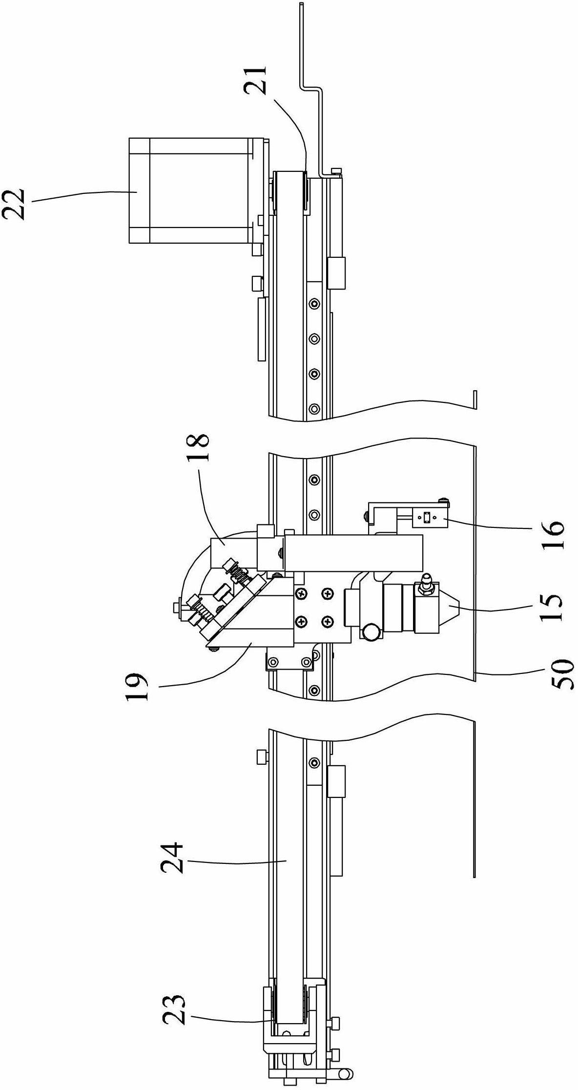
[0020] The laser cutting head 10 for laser processing equipment is installed on the beam 20 of a laser processing equipment and can move horizontally along the beam 20. One end of the beam 20 is provided with a driving pulley 21 and a motor 22, the other side of the beam 20 One end is provided with a driven pulley 23, and a timing belt 24 is sleeved between the driving pulley 21 and the driven pulley 23. The laser cutting head 10 is connected with the timing belt 24, and the movement of the timing belt 24 is driven by a motor to realize laser cutting. The cutting head 10 moves horizontally along the beam 20 .

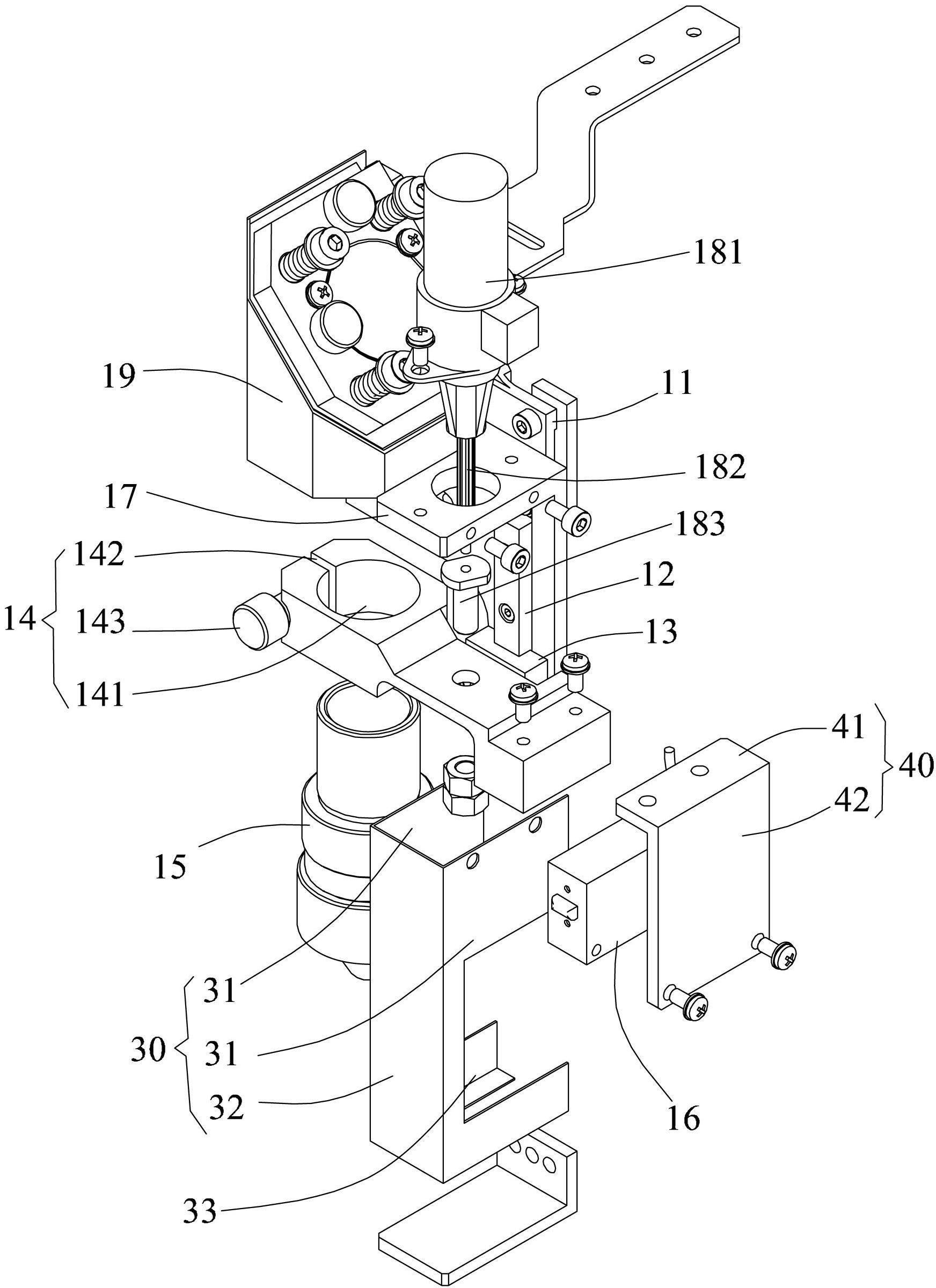
[0021] The laser cutting head 10 for laser processing equipment includes a mounting block 11, a linear guide rail 12, a slider 13, a focusing tube fixing plate 14, a focusing tube 15, a focus sensor 1...


PUM


Abstract

The invention relates to a laser cutting head for laser machining equipment, which comprises a mounting block, a linear guide rail, a sliding block, a focusing tube fixing plate, a focusing tube, a focal length sensor, a motor fixing plate, a linear motor, and a microscope base. The linear guide rail is vertically fixed on the mounting block; the sliding block is glidingly installed on the near guide rail; the focusing tube fixing plate is fixed on the sliding block; the focusing tube and the focal length sensor are respectively fixed on two sides of the focusing tube fixing plate; the motor fixing plate and the microscope base are fixed at the upper end of the mounting block and positioned above the linear guide rail; the linear motor comprises a motor body, a screw rod connected with the motor body and positioned on the lower side of the motor body, and a nut sleeved on the screw rod; the motor body is fixed on the motor fixing plate; and the nut is fixed with the sliding block. The laser cutting head can realize automatic focusing and defocusing, and has a simple structure and is low in cost.

Description

technical field [0001] The invention relates to a component of laser processing equipment, in particular to a laser cutting head used in the laser processing equipment. Background technique [0002] At present, the laser cutting heads of low-end laser engraving and cutting machines are all fixed. When engraving is required, the focus is usually adjusted manually. Manual focus has the following disadvantages: 1. Low processing efficiency; 2. Manual adjustment errors are likely to cause product processing quality problems; 3. In some occasions that require automatic switching between focus and defocus, manual adjustment cannot complete the accurate switch of focal length. Although some high-end laser cutting models have auto-focus function, the mass and cost of the focusing module is too high, so it is not suitable for low-end laser engraving equipment that needs to run at high speed. Contents of the invention [0003] Therefore, the purpose of the present invention is to p...

Claims


Application Information

Patent Timeline
Patent Type & Authority Applications(China)
IPC IPC(8): B23K26/04B23K26/36B23K26/046B23K26/38
Inventor 朱冉王亮倪伟平
Owner 江苏大族粤铭激光科技有限公司
Why Eureka
Try Eureka