
Hand-driven mechanical grounder device
A hand-crank, rolling ball technology, applied in sports accessories, indoor games, etc., can solve problems such as reduced willingness and ability to operate, disadvantage of children, lack of communication, etc., to achieve a small footprint, improve thinking and motor nerves, The effect of easy disassembly
- Summary
- Abstract
- Description
- Claims
- Application Information
AI Technical Summary
Problems solved by technology
Method used
Image

Examples
Embodiment Construction
[0019] The present invention will be described in more detail below in conjunction with the accompanying drawings and embodiments.
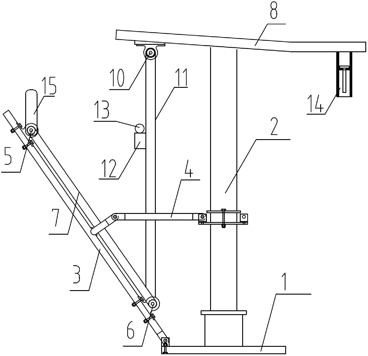
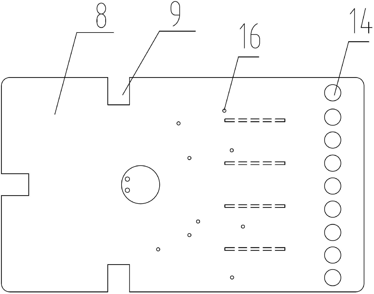
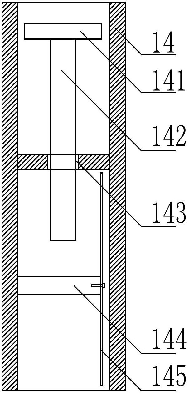
[0020] Such as figure 1 As shown, the present invention is a hand-operated mechanical ball rolling device, comprising a base 1 on which a vertical main support rod 2 and two oblique secondary support rods 3 are fixed, and the main support rod 2 is connected with each auxiliary support rod. The support rods 3 are connected by the connecting shaft 4, and the upper and lower ends of each secondary support rod 3 are respectively provided with an upper pulley 5 and a lower pulley 6, the upper pulley 5 is fixed with a hand rocker 15, the upper pulley 5 and the lower pulley The first synchronous belt 7 is arranged between the wheels 6, and the top of the main support rod 2 is fixedly connected with a pallet 8 with two gaps 9. The structure of the pallet 8 is as follows: figure 2 As shown, it is provided with an obstacle 16 that changes the trajectory ...
PUM
 Abstract
Description
Claims
Application Information