LED linear driving circuit applicable to thyristor dimmer and control method

An LED drive and linear drive technology, applied in the direction of electric lamp circuit layout, light source, electric light source, etc., can solve the problems of lamp flickering and failure to work normally, and achieve the effect of improving efficiency, increasing total output lumens, and improving utilization rate.

Inactive Publication Date: 2012-09-12
SHANGHAI BRIGHT POWER SEMICONDUCTOR CO LTD
View PDF6 Cites 21 Cited by
  • Summary
  • Abstract
  • Description
  • Claims
  • Application Information

AI Technical Summary

Problems solved by technology

When the thyristor dimmer is used in the LED drive circuit, because of the nonlinearity of the LED load, the load current will not exist at any phase-cut angle, so the dimmer often works in an abnormal state, causing the light to flicker doesn't even work

Method used


Image

  • LED linear driving circuit applicable to thyristor dimmer and control method
  • LED linear driving circuit applicable to thyristor dimmer and control method
  • LED linear driving circuit applicable to thyristor dimmer and control method

Examples


Embodiment Construction

[0022] Specific embodiments of the present invention will be described in detail below in conjunction with the accompanying drawings.

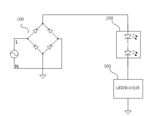
[0023] In the traditional LED linear constant current circuit, the LED light string will only be lit when the input voltage reaches the peak value.

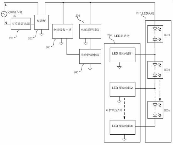
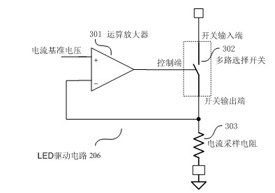
[0024] The invention provides an LED linear current drive circuit, which can light up some LEDs when the input voltage is low, thereby improving the utilization rate of the LEDs, and at the same time, turn on or turn off the current absorbing circuit according to the output voltage signal of the rectifier bridge to achieve compatibility. purpose of silicon controlled dimmers. The present invention is characterized in that it includes: an LED lamp load, the LED lamp load is composed of N groups of LEDs in series; an LED driver, the LED driver is composed of N LED driving circuits, to control the operation or shutdown of a single or all LED groups; A voltage sampling network is used to detect the ...


PUM


Abstract

The invention discloses an LED linear driving circuit applicable to a thyristor dimmer and a control method. The thyristor dimmer is connected with an input end of the LED linear driving circuit through a rectifier bridge. The LED linear driving circuit is characterized by comprising an LED light string, an LED driver, a voltage sampling network, an absorption control circuit and a current absorption circuit, the LED light string is formed by serially connecting at least one LED, the LED driver comprises N LED driving circuits, each LED driving circuit is connected with cathodes of a group of LED loads so as to control on or off of single or all LED groups, the voltage sampling network is used for detecting output voltage of the rectifier bridge and outputting a signal, the absorption control circuit is used for controlling the current absorption circuit according to the output signal of the voltage sampling network, and the current absorption circuit is used for providing the thyristor dimmer with stable holding current.

Description

technical field [0001] The invention relates to a linear LED driving circuit, in particular to an LED lighting driving circuit and a control method suitable for dimming by a thyristor dimmer. Background technique [0002] figure 1 It is a traditional LED linear constant current control circuit. In the figure, the LED lamp string 101 is connected to the positive terminal of the input rectifier bridge 100 , and the current flowing through the LEDs is set through an LED driving circuit 102 connected to the ground terminal of the input rectifier bridge 100 . The positions of the LED light string 101 and the linear constant current source 102 can be interchanged. [0003] Since the LED light string 101 is composed of many LEDs in series, the LED light string 101 will be lit only when the input voltage is higher than the forward conduction voltage of the LED light string 101 . In a system powered by AC mains, the LED light string 101 will be lit only when the input voltage reac...

Claims


Application Information

Patent Timeline
Patent Type & Authority Applications(China)
IPC IPC(8): H05B37/02
Inventor 胡黎强于得水
Owner SHANGHAI BRIGHT POWER SEMICONDUCTOR CO LTD
Why Eureka
Try Eureka