Method for taking cooling pipe network as building bottom plate multi-layer reinforced support frame

A technology of cooling pipes and support frames, which is applied in the processing of building materials, construction, building construction, etc. It can solve the problems of difficult control of the quality of on-site butt joints of steel pipe columns, high requirements for hoisting precision of steel pipe columns, and difficulties in thermal insulation and maintenance of ground beams. Achieve the effect of convenient and quick dismantling, ensure the quality of pouring, and avoid the sinking of steel bars

Active Publication Date: 2012-10-03
CHENGDU SIXTH CONSTR ENG
View PDF6 Cites 6 Cited by
  • Summary
  • Abstract
  • Description
  • Claims
  • Application Information

AI Technical Summary

Problems solved by technology

The disadvantage of this method is that the operator needs to work in the steel cage on the bottom plate when laying the insulation pipe, placing the I-beam or steel bar support and removing the steel pipe frame. The construction is not easy to operate and is very dangerous. The cost is high, and a special method is required for fixing
Moreover, the construction process is complicated, there are many interspersed procedures, the hoisting precision of the steel pipe column is high, and the quality of the on-site butt joint of the steel pipe column is not easy to control
The top surface of the foundation is reversed on the ground beam of the foundation, and the composite stirrup of the ground beam passes through the top surface of the bottom plate of the foundation to connect the upper and lower steel bars. Since the foundation girder is poured twice, it is very difficult to maintain the insulation and maintenance of the ground beam

Method used


Image

  • Method for taking cooling pipe network as building bottom plate multi-layer reinforced support frame
  • Method for taking cooling pipe network as building bottom plate multi-layer reinforced support frame
  • Method for taking cooling pipe network as building bottom plate multi-layer reinforced support frame

Examples


Embodiment Construction

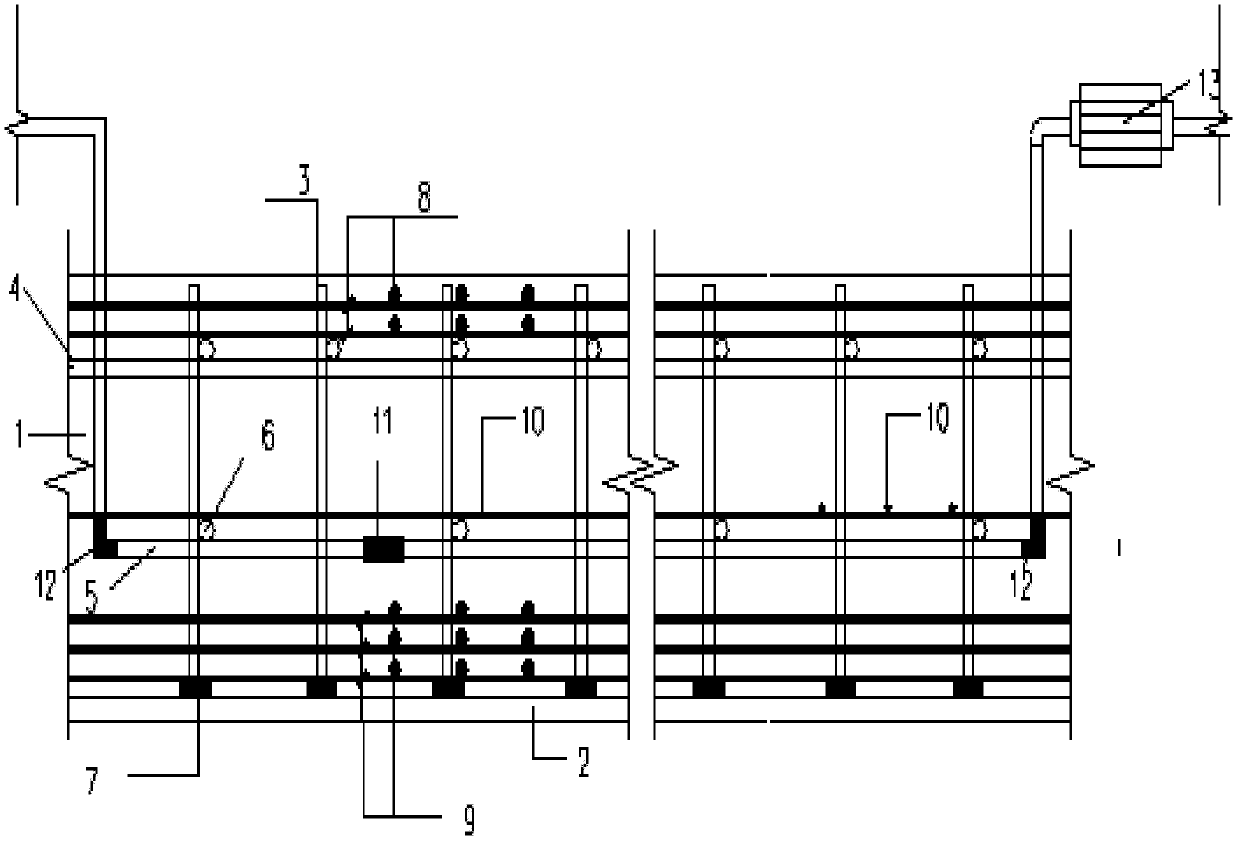
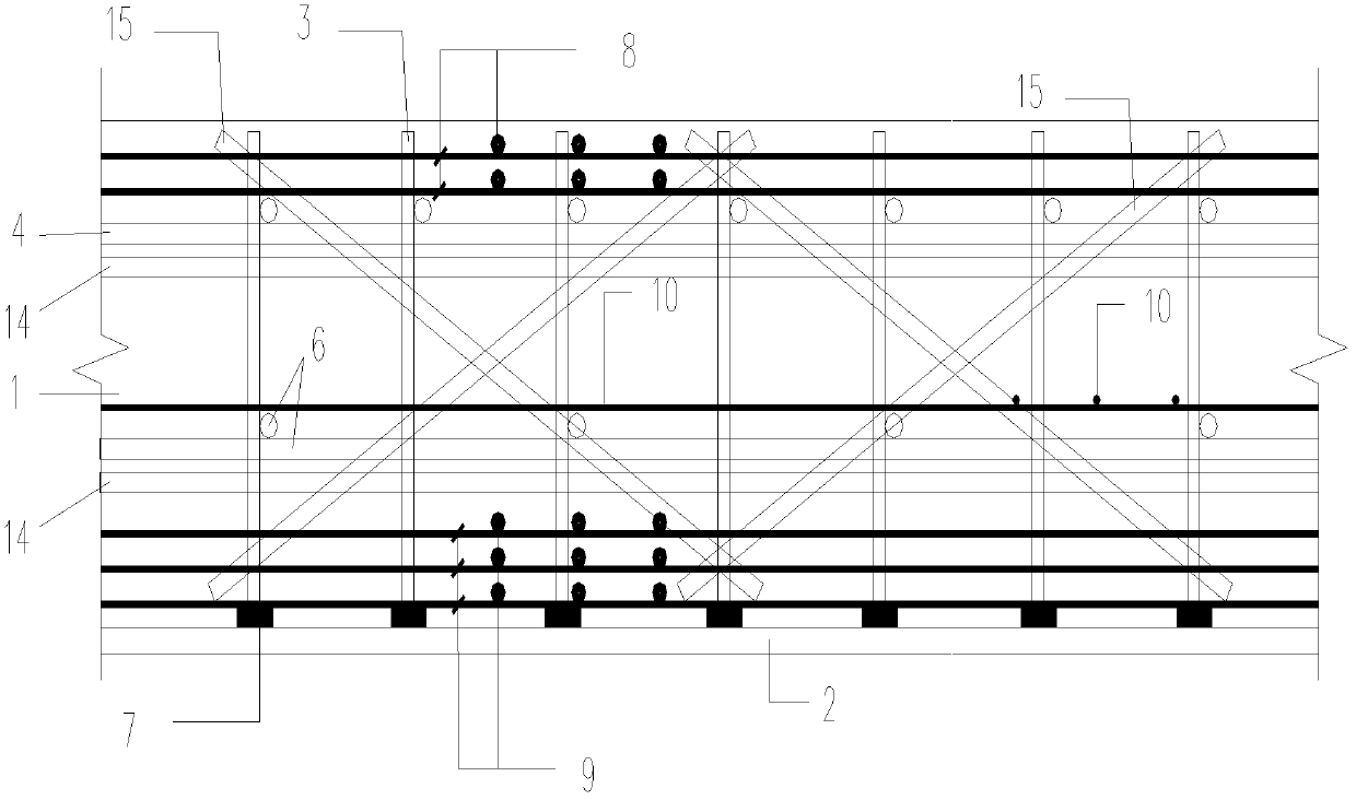
[0012] refer to figure 1 , figure 2 . In the cooling steel pipe network support system for the construction of multi-layer steel bars on a large-volume concrete floor described below, the fastener steel pipe frame is erected on the concrete floor 1 . Connect vertical rod 3 steel pipes and horizontal rod steel pipes with fasteners, base plate middle part reinforcement 10, base plate top reinforcement 8 are bound on the middle part horizontal rod 6 and the upper horizontal rod 4 of fastener steel pipe frame respectively. The middle horizontal rods 6 arranged in a line or matrix in the middle of the fastener steel frame are connected by quick connectors to form a closed pipe. The fastener steel pipe frame starts from the edge of the raft bottom plate to set up steel pipe supports to support the middle steel bar 10 and the upper steel bar 8 of the concrete bottom plate. After binding the steel bars of the concrete floor, use fastener steel pipes to set up steel pipe supports f...


PUM


Abstract

The invention provides a method for taking a cooling pipe network as a building bottom plate multi-layer reinforced support frame and aims to provide a method for building bottom plate reinforced support frame, which is fast in construction progress, low in construction cost and high in safety. The method is realized by the following steps of: erecting a fastening steel pipe frame on a concrete bottom plate (1); connecting an upright rod (3) steel pipe and a horizontal rod steel pipe with a fastener, and respectively binding and placing the steel bars (10) in the middle of the bottom plate and the steel bars (8) on the upper part of the bottom on a horizontal rod (6) in the middle of the fastening steel pipe frame and a horizontal rod (4) on the upper part of the fastening steel pipe frame; erecting the steel pipe frame from the edge of a raft board for supporting by employing the fastening steel pipes after the bottom plate steel bars are bound, and continuously arranging vertical diagonal bridging (15) and two pieces of horizontal diagonal bridging (14) which are arranged on the upper and lower parts according to the column space at the periphery of the raft board; and taking the horizontal rod in the middle of the fastening steel pipe frame as a large-volume concrete cooling pipe, mounting a pressure pump at one end of a middle horizontal rod (5) serving as the cooling pipeso as to inject cold water into the pipeline, and taking the other end of the middle horizontal rod as a water outlet.

Description

technical field [0001] The invention relates to a method in which a mass concrete (mass concrete) cooling pipe network doubles as a multi-layer steel bar support frame for a building floor. Mass concrete: Mass concrete in which the minimum dimension of the concrete structure is not less than 1 meter, or concrete that is expected to cause harmful cracks due to temperature changes and shrinkage caused by hydration of the cementitious materials in the concrete. Mass concrete generally refers to the concrete whose pouring volume is greater than 1000 m3 or the minimum size of the concrete structure entity is equal to or greater than 2 m, and the concrete pouring needs to study the temperature control measures. Background technique [0002] In recent years, with the rapid development of the construction industry, mass concrete has been used more and more widely. For example, concrete dams and basement concrete floors of high-rise buildings are all poured with mass concrete. The c...

Claims


Application Information

Patent Timeline
Patent Type & Authority Applications(China)
IPC IPC(8): E02D15/00E02D15/02E02D29/045E04G21/02
Inventor 张静彭传科黄良曾伟车汪速陈珂
Owner CHENGDU SIXTH CONSTR ENG
Why Eureka
Try Eureka