Polarity-reversal voltage generator based on direct current high voltage cascade generation circuit

A voltage generating device and a technology for generating DC high voltage, applied in the field of polarity reversal voltage generating devices, can solve the problems of high cost and difficulty in generating higher voltages, and achieve the effects of reducing insulation requirements, improving DC voltage levels, and reducing costs

Inactive Publication Date: 2013-03-20
HARBIN UNIV OF SCI & TECH
View PDF4 Cites 12 Cited by
  • Summary
  • Abstract
  • Description
  • Claims
  • Application Information

AI Technical Summary

Problems solved by technology

[0003] The purpose of the present invention is to solve the problem that the existing polarity reversal voltage generating device is difficult to generate higher

Method used


Image

  • Polarity-reversal voltage generator based on direct current high voltage cascade generation circuit
  • Polarity-reversal voltage generator based on direct current high voltage cascade generation circuit
  • Polarity-reversal voltage generator based on direct current high voltage cascade generation circuit

Examples


specific Embodiment approach 1

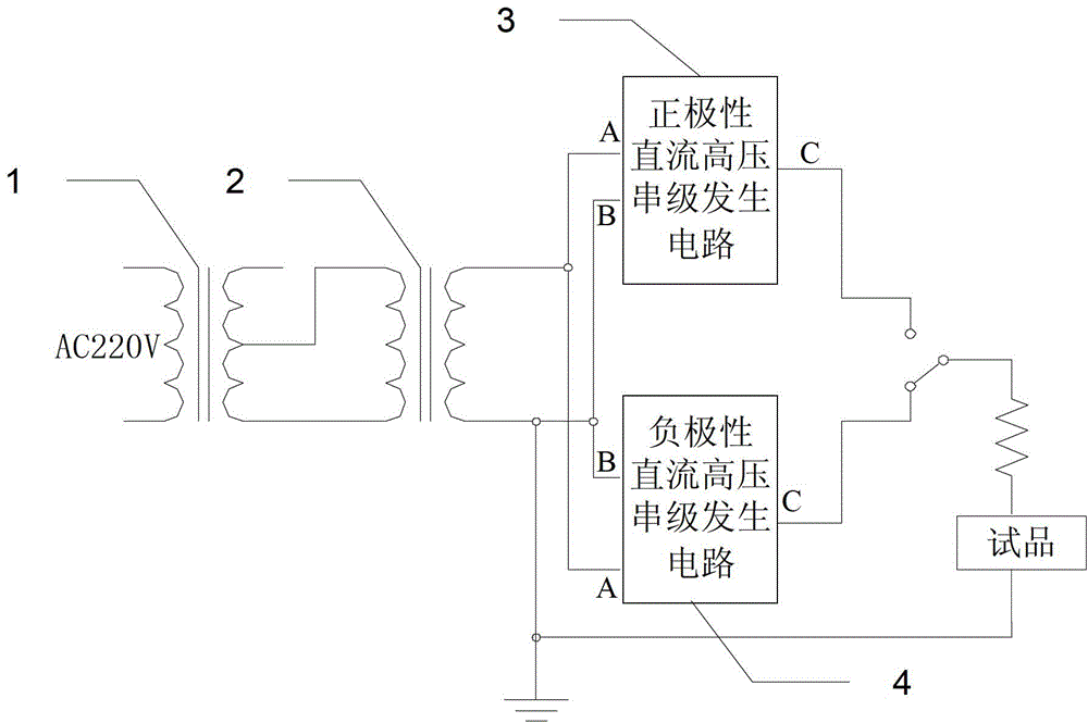
[0010] Specific implementation mode 1: Combination figure 1 To explain this embodiment, the polarity reversal voltage generating device based on the DC high voltage cascade generating circuit described in this embodiment includes a voltage regulator 1, a step-up transformer 2, a positive polarity DC high voltage cascade generating circuit 3, and a negative electrode. High-voltage cascade generation circuit 4, single-pole double-throw switch and protection resistor;

[0011] Both ends of the primary coil of the voltage regulator 1 are used to input single-phase alternating current signals, one end of the secondary coil of the voltage regulator 1 is connected to one end of the primary coil of the step-up transformer 2, and the secondary side of the voltage regulator 1 The adjustable end of the coil is connected to the other end of the primary coil of the step-up transformer 2, and one end of the secondary coil of the step-up transformer 2 is simultaneously connected to the signal i...

specific Embodiment approach 2

[0013] Embodiment 2: This embodiment is a further limitation to the polarity reversal voltage generating device based on the DC high voltage cascade generating circuit described in Embodiment 1.

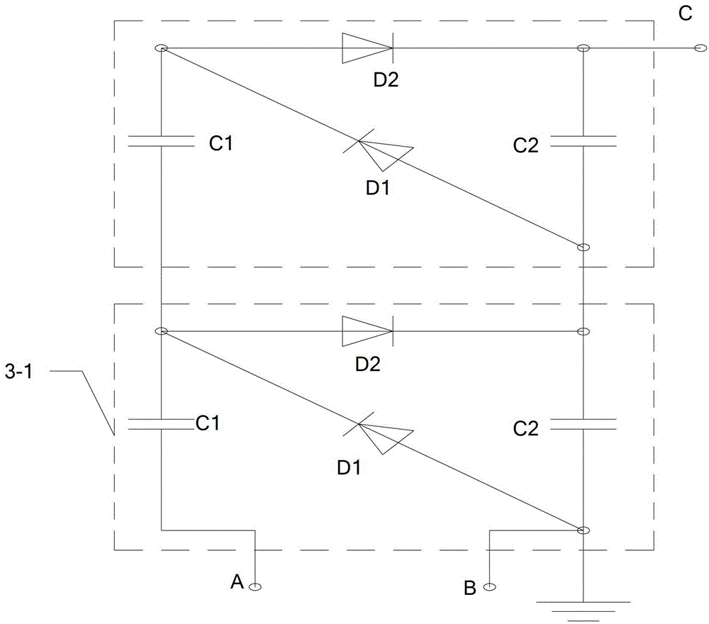
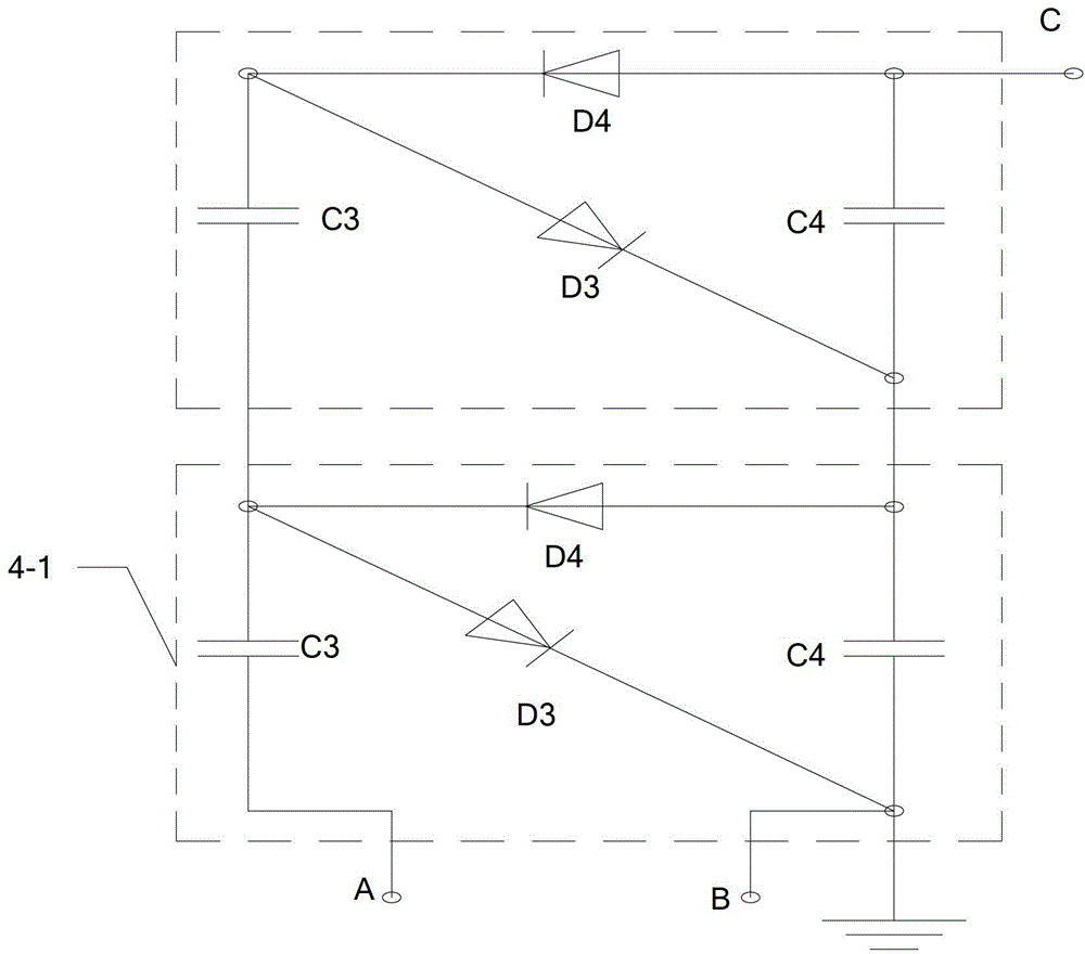
[0014] The positive polarity direct current high voltage cascade generating circuit 3 is composed of N positive polarity direct current high voltage generating circuits 3-1 in series, and N is a positive integer greater than 1.

[0015] When it is necessary to increase the DC voltage level, it is achieved by increasing the number of stages of the DC high-voltage series pole generating circuit.

specific Embodiment approach 3

[0016] Specific implementation mode three: combination figure 2 To illustrate this embodiment, this embodiment is a further limitation on the polarity reversal voltage generating device based on the DC high voltage cascade generating circuit described in the second embodiment.

[0017] The positive DC high voltage cascade generating circuit 3 is composed of two positive DC high voltage generating circuits 3-1 in series.


PUM


Abstract

The invention relates to a polarity-reversal voltage generator based on a direct current high voltage cascade generation circuit. The polarity-reversal voltage generator solves the problems that the existing polarity-reversal voltage generator cannot generate higher voltage and is higher in cost. After being subjected to voltage regulation by a voltage regulator, single-phase alternating current is input to a boosting transformer to generate high voltage alternating current; the high voltage alternating current is connected with a positive-polarity direct current high voltage cascade generation unit and a negative-polarity direct current high voltage cascade generation unit respectively to generate positive-polarity direct current voltage and negative-polarity direct current voltage; a voltage polarity of a tested article is selected for connection in a manner that a single-pole double-throw switch is selectively connected with an output end of the positive-polarity direct current high voltage cascade generation unit or an output end of the negative-polarity direct current high voltage cascade generation unit; after the voltage polarity is selected, the voltage is connected with one end of the tested article through a protective resistor; and the other end of the tested article is earthed, so that the voltage is applied across the tested article. The polarity-reversal voltage generator is used for a converter transformer.

Description

Technical field [0001] The invention relates to a polarity reversal voltage generating device, in particular to a polarity reversal voltage generating device based on a DC high voltage cascade generating circuit. Background technique [0002] With the continuous growth of the national economy and the increasing demand for energy, high-voltage long-distance power transmission has become a strategic issue affecting economic development. The Office of the National Energy Leading Group listed the construction of UHV grids as a key point of energy work. In UHV long-distance transmission lines, DC transmission has obvious advantages, so DC transmission will play an increasingly important position in the transmission network. The converter transformer is a crucial equipment in the DC transmission system, and it is also the core equipment for connecting the converter station and inverter station at both ends of the AC and DC transmission system. Due to the particularity of the operatin...

Claims


Application Information

Patent Timeline
IPC IPC(8): H02M7/06
Inventor 池明赫陈庆国高源魏新劳王永红聂洪岩
Owner HARBIN UNIV OF SCI & TECH
Why Eureka
Try Eureka