
A Servo Control System and Method for Eliminating Torsional Vibration of Ring Spinning Frame Rollers
A servo control system and spinning frame technology, applied to spinning machines, continuous winding spinning machines, textiles and papermaking, etc., can solve problems such as economic loss, roller torsional deformation, etc., to prolong service life and eliminate roller torsion Vibration, reduce the effect of the load
- Summary
- Abstract
- Description
- Claims
- Application Information
AI Technical Summary
Problems solved by technology
Method used
Image

Examples
Embodiment Construction
[0012] Below in conjunction with accompanying drawing, the present invention will be further described.
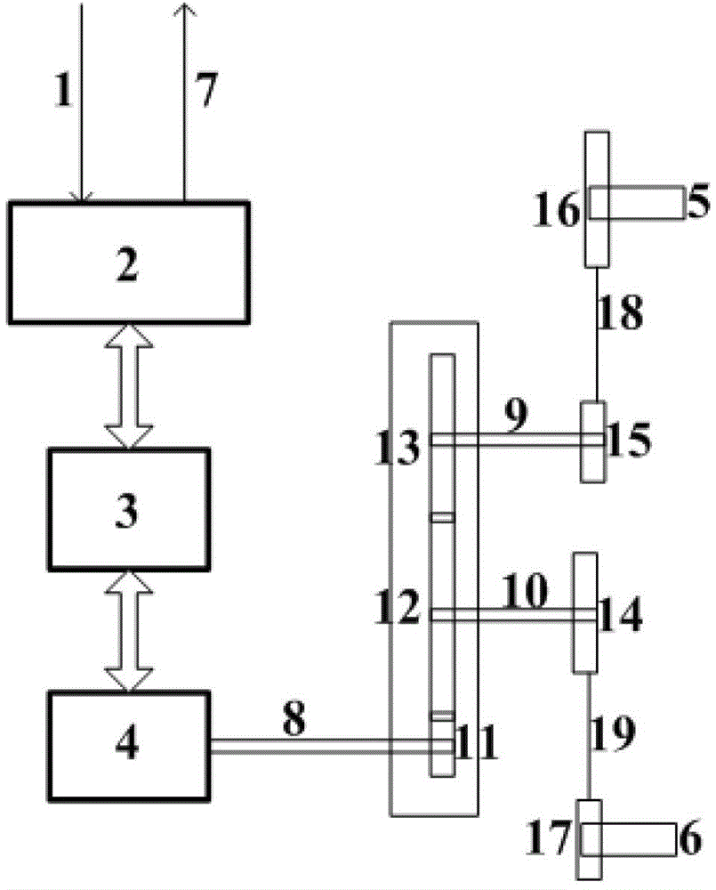
[0013] Such as figure 1 As shown, a servo control system capable of eliminating roller torsional vibration includes a servo driver 3, a servo motor 4, and a programmable logic controller 2, wherein the servo motor 4 drives the gear 11 through the motor shaft 8, and the gear 11 and the gear 12 are meshed with each other. , the gear 12 is connected with the gear 14 through the connecting shaft 10, and the gear 14 drives the gear 17 on the left-hand front roller 6 through the synchronous belt 19, and finally realizes the torque compensation of the servo motor 4 to the left-hand front roller 6, the gear sets 11 and 12 and the gear set 14 and 17 jointly realize the deceleration control; the gear 12 and the gear 13 are meshed and connected with each other, the gear 13 is connected with the gear 15 through the connecting shaft 9, and the gear 15 drives the gear 16 on the right-ha...
PUM
 Abstract
Description
Claims
Application Information