
Test stand having a vibration damper

a technology of vibration dampener and test stand, which is applied in the field of test stand, can solve the problems of affecting the accuracy of measurement results, so as to reduce the interference of resonance frequencies

Inactive Publication Date: 2014-09-02
HORIBA EURO
View PDF26 Cites 0 Cited by
  • Summary
  • Abstract
  • Description
  • Claims
  • Application Information

AI Technical Summary

Benefits of technology

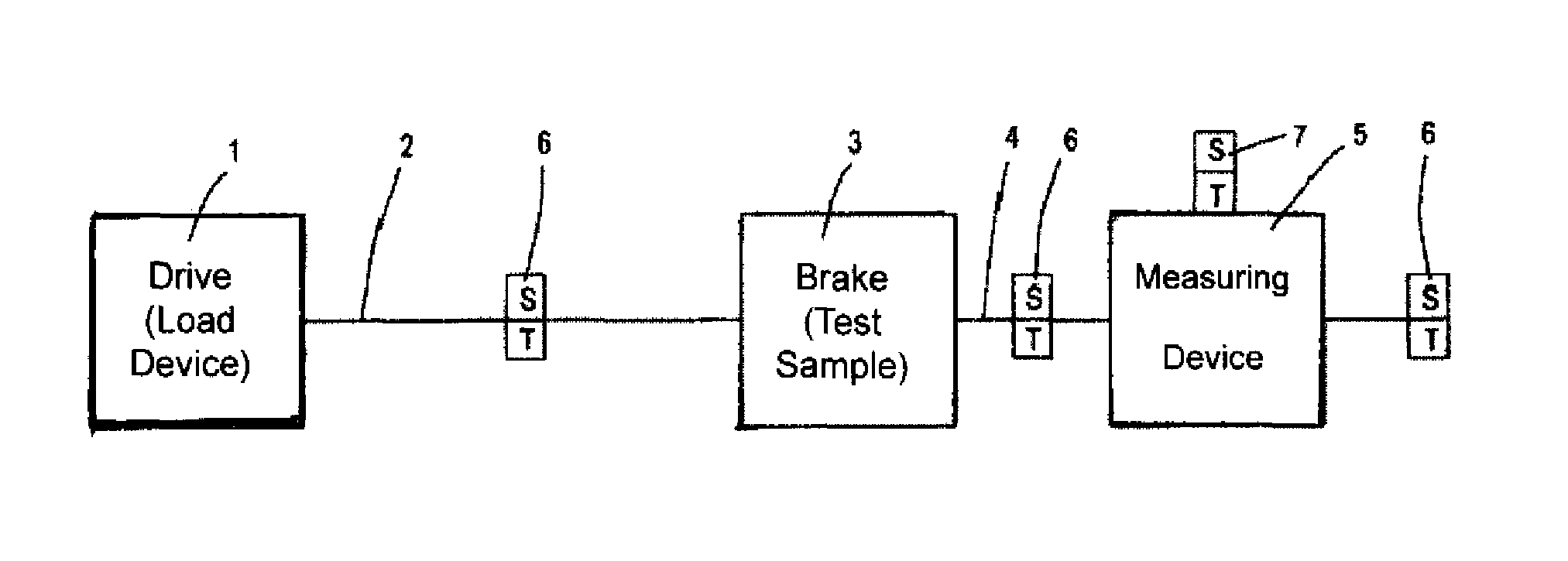
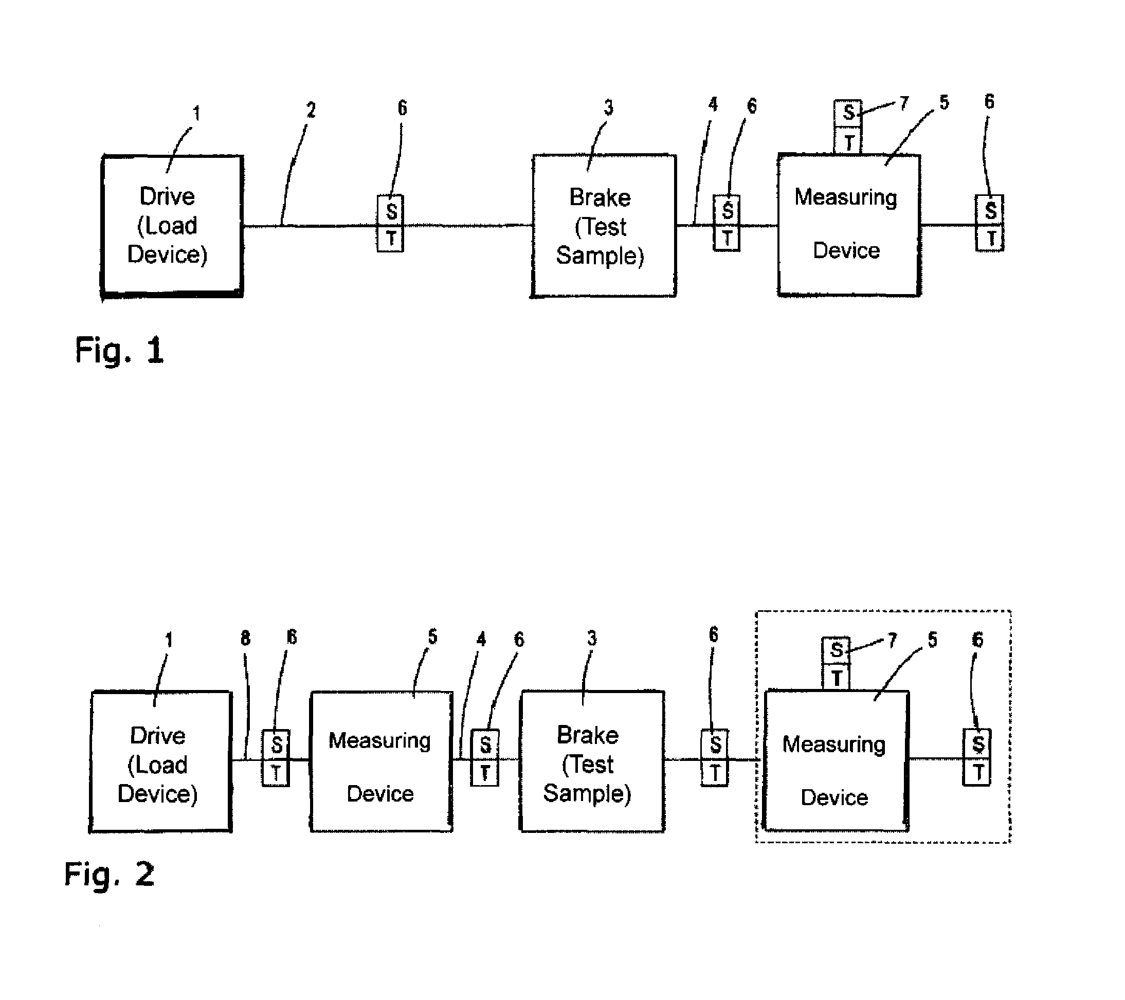
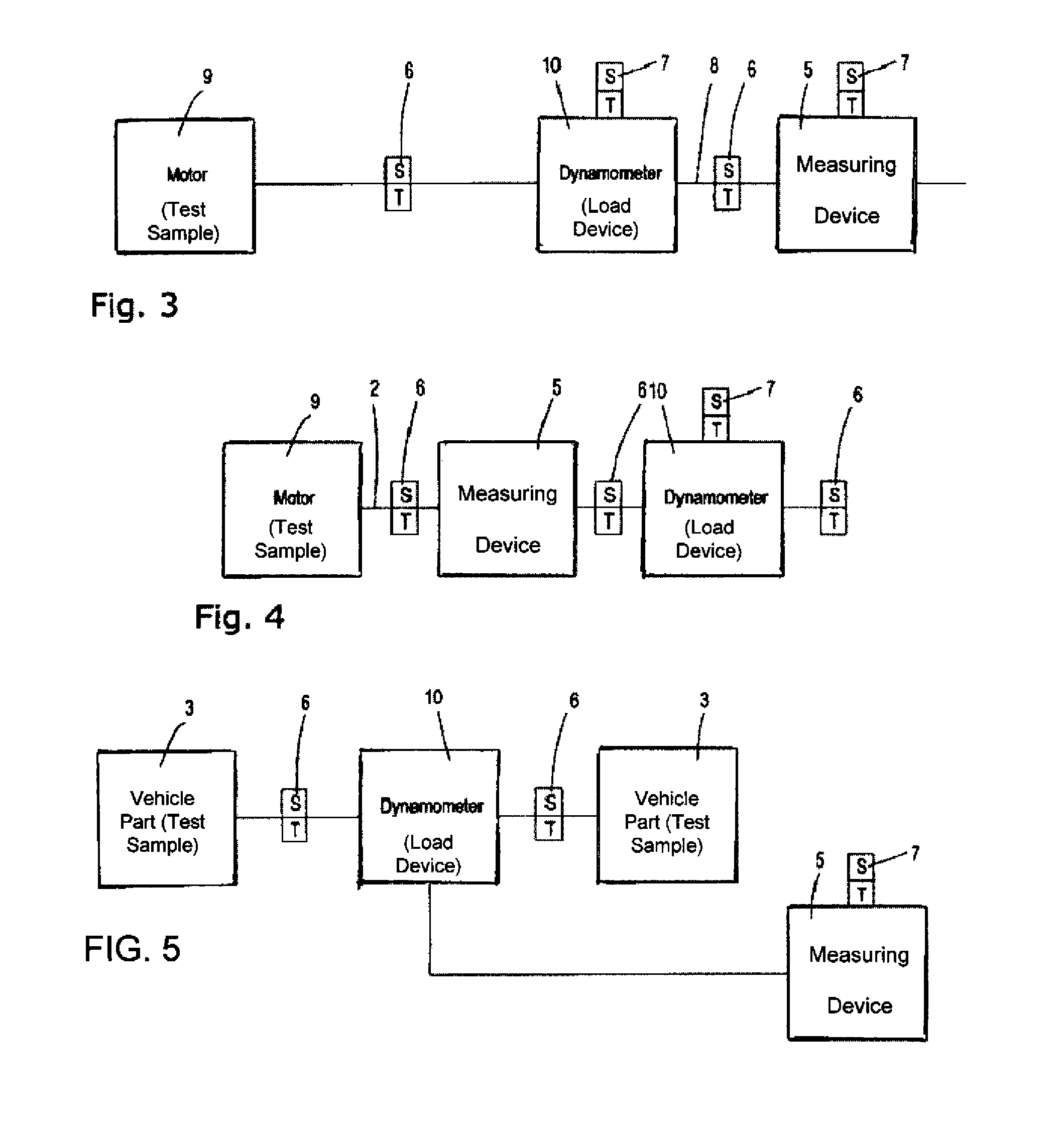
[0019]A classic test stand is thus specified according to the invention, in which provision is additionally made for a vibration damping device (hereinbelow also referred to as vibration damper). A vibration damper (e.g., a tuned mass damper—TMD) is an undamped or damped spring-mass system comprising mechanics, which provides an auxiliary oscillator, which can considerably reduce the amplitude of a system, which vibrates in response to a resonance frequency. The vibration damper is coupled to the system, which is to be steadied, in that it is fastened at a suitable location—sensibly at a location comprising a high vibration amplitude.
[0022]The vibration damper makes it possible for resonances to be damped considerably or even eliminated completely in the range of a natural frequency of a system, which is to be steadied, depending on the adjustment of the system.
[0023]The vibration damper is not to be disposed in the flux of force between the components of the test stand. However, it can easily be installed in the immediate vicinity of components, which are located in the flux of force.
[0026]Provision can easily be made in the test stand for a plurality of vibration damping devices—also comprising different designs—which are disposed at different locations on the test stand. In this manner, it is possible to dispose of interfering amplitudes and resonance frequencies.
[0029]In an alternative case of the test stand, provision is made for at least one linear vibration damper and for at least one torsional vibration damper. Torsional vibrations in the drive train, in particular, between load device and test specimen, can be eliminated in this manner, while the linear vibration damper can be provided at a force-measuring device, which belongs to the measuring device.

Problems solved by technology

Due to the fact that the test specimens can be operated in a wide speed range, it cannot be avoided that the vibrations generated by the test specimens coincide with resonance frequencies of other components of the test stand.
The excitation of a component with a frequency in the natural frequency or resonance range, respectively, leads to an excessively strong vibration loading of the respective component and of the adjacent aggregates, whereby parts of the test stand can be damaged, but, at least, measuring results can be distorted.
In the event that vibrations, which coincide with resonance vibrations from one of the components, in particular, the measuring device, are generated during the operation of the test stand, strong vibration exaggerations occur at the respective component, which distort the measuring result or even make it impossible to measure the actual load.
For the most part, measures for shifting the frequencies into overcritical or subcritical frequency ranges are not helpful in the case of test stands, because the test specimens are to be tested under conditions that are as real as possible.
The damping of the vibrations with the help of a coupling or compensating coupling, respectively, in the drive train or the reduction of the excitation (changing the test specimen itself) is also not acceptable in practice, because it calls into question the capability to transfer the test stand results to actual practice.

Method used


Image

  • Test stand having a vibration damper
  • Test stand having a vibration damper
  • Test stand having a vibration damper

Examples


Embodiment Construction

[0066]As required, detailed embodiments of the present invention are disclosed herein; however, it is to be understood that the disclosed embodiments are merely exemplary of the invention, which can be embodied in various forms. Therefore, specific structural and functional details disclosed herein are not to be interpreted as limiting, but merely as a basis for the claims and as a representative basis for teaching one skilled in the art to variously employ the present invention in virtually any appropriately detailed structure. Further, the terms and phrases used herein are not intended to be limiting; but rather, to provide an understandable description of the invention. While the specification concludes with claims defining the features of the invention that are regarded as novel, it is believed that the invention will be better understood from a consideration of the following description in conjunction with the drawing figures, in which like reference numerals are carried forwar...


PUM


Abstract

A rotation test stand for a test specimen includes a load device for generating a load for the test specimen, a test specimen accommodation for accommodating the test specimen and for transmitting the load to the test specimen as well as a measuring device for measuring a measured variable acting on the test specimen. Provision is furthermore made at a suitable location for a vibration damping device for damping vibrations, which arise in the test stand. The vibration amplitudes are to be reduced, in particular, by a torsional vibration damper or a linear vibration damper. The vibration damper can be disposed in the drive train or at the measuring device.

Description

CROSS-REFERENCE TO RELATED APPLICATIONS[0001]This is a continuing application, under 35 U.S.C. §120, of copending International Application No. PCT / EP2010 / 004510, filed Jul. 22, 2010, which designated the United States and was not published in English; this application also claims the priority, under 35 U.S.C. §119, of German Patent Application No. 10 2009 038 849.4, filed Aug. 26, 2009; the prior applications are herewith incorporated by reference in their entirety.STATEMENT REGARDING FEDERALLY SPONSORED RESEARCH OR DEVELOPMENT[0002]Not ApplicableFIELD OF THE INVENTION[0003]The present invention lies in the field of test stand. The present disclosure relates to a test stand having a vibration dampener. The invention relates to a rotation test stand for a test specimen.BACKGROUND OF THE INVENTION[0004]Such test stands are used, in particular, for testing vehicles and vehicle components, such as, e.g., internal combustion engines, drive trains and brakes. The test specimen is thereby...

Claims


Application Information

Patent Timeline
Patent Type & Authority Patents(United States)
IPC IPC(8): G01M15/00
CPCG01L3/16
Inventor LEE, JOON-KYU
Owner HORIBA EURO
Learn More