Magnetic control device for timepiece

a control device and timepiece technology, applied in the direction of electric winding, instruments, horology, etc., can solve the problems of not being able to reduce the size of the prior art device, certain defects in the device, etc., and achieve the effect of reducing the cost price and being more compa

Active Publication Date: 2008-07-29
THE SWATCH GRP RES & DEVELONMENT LTD
View PDF9 Cites 92 Cited by
  • Summary
  • Abstract
  • Description
  • Claims
  • Application Information

AI Technical Summary

Benefits of technology

[0010]Contrary to the watch casing itself, the sealed tube is protected from possible impacts. The wall of the tube therefore does not need to be as thick as the exterior wall of the timepiece. Hence it is possible to arrange the reed contacts at a small distance from the trajectory of the magnet, in a high field gradient zone. As a consequence, an advantage of the present invention resides in the possibility of providing a device which is capable of detecting even a small displacement of the magnet.
[0011]Another advantage of the present invention is that the stem and the first magnet are inserted into the sealed tube. In these conditions, only the end of the stem which emerges from the timepiece is visible. Hence, the magnet and the remainder of the control device are not visible. It is therefore possible to provide a control device which has the appearance of a traditional control stem.
[0012]Another advantage of the present invention is that two magnetic sensors suffice to allow the electronic means to distinguish three positions of the first magnet (and even four positions according to one variant). Thanks to this feature, the control device according to the invention can be more compact. On the other hand, the fact of limiting the number of magnetic sensors makes it possible to reduce the cost price.
[0013]According to an advantageous variant of the present invention, the positions of the first and of the second reed contact are offset angularly relative to the axis of the sealed tube. The contacts therefore not being disposed in the extension one of the other, free choice of their spacing in the direction of the longitudinal axis of the stem is possible, without having to take into account possible interferences between contacts. According to this variant, it is therefore possible to produce a control device within which the amplitude of the translational movement which the control member must perform is reduced to the minimum.

Problems solved by technology

This device of prior art has certain defects.
Furthermore it does not appear that it is possible to reduce greatly the size of this prior art device.

Method used


Image

  • Magnetic control device for timepiece
  • Magnetic control device for timepiece
  • Magnetic control device for timepiece

Examples


Embodiment Construction

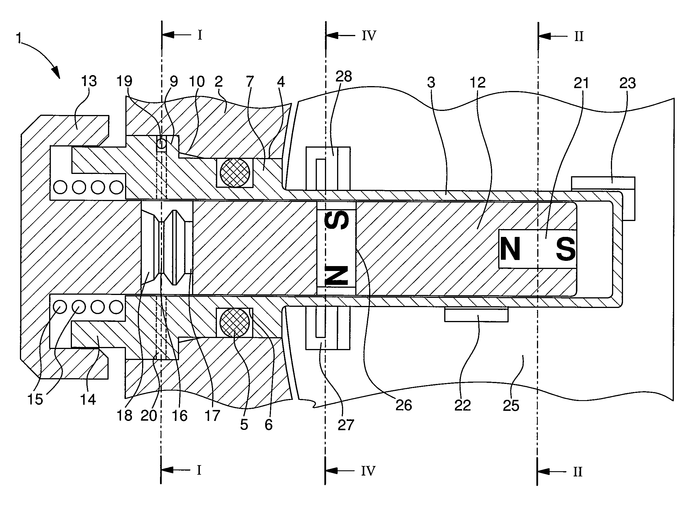
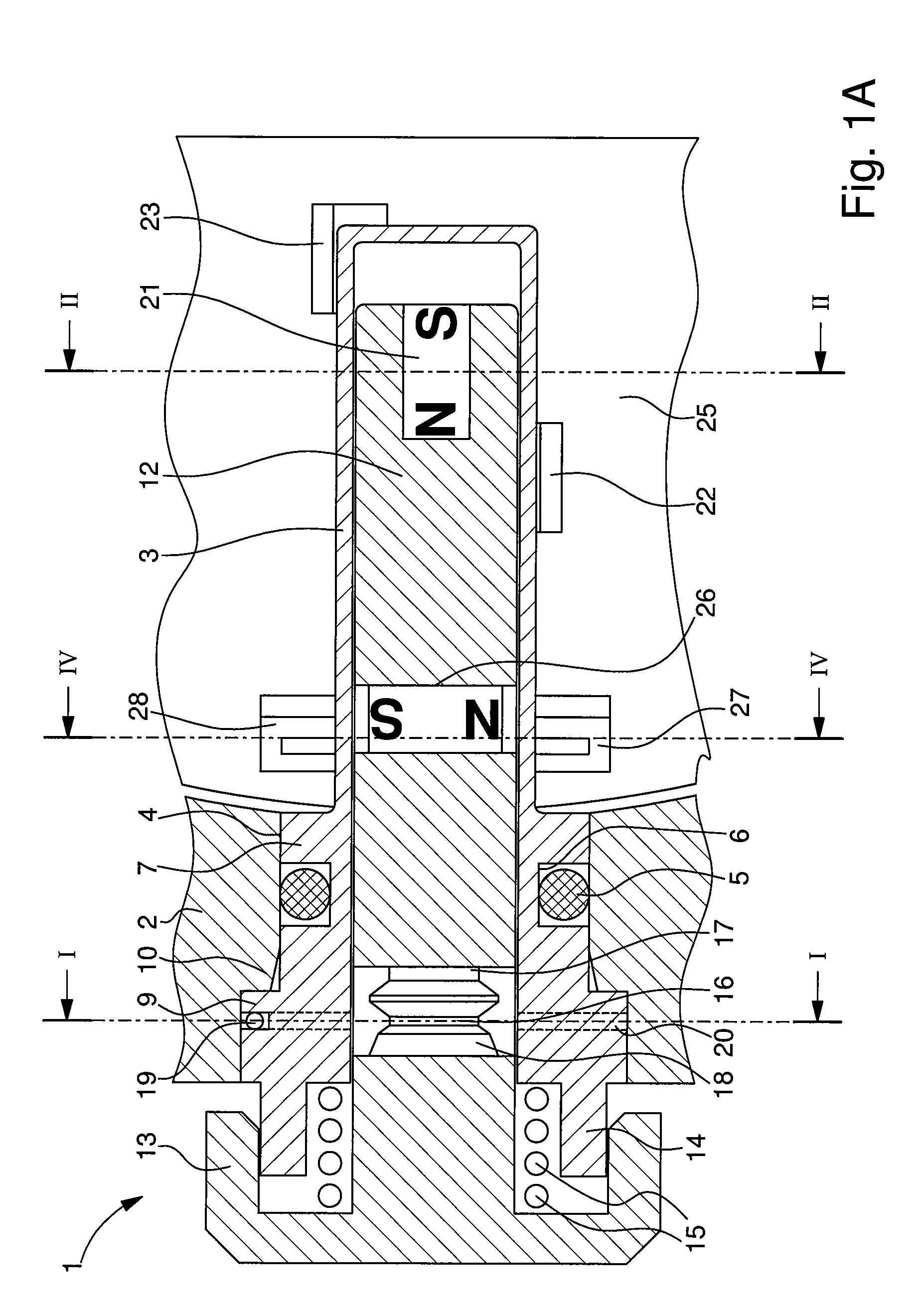
[0023]FIG. 1A represents a particular embodiment of the control device according to the present invention. In this example, the magnetic control device 1 is mounted in the middle part 2 of a watch. It can be seen in the drawing that a tube (reference number 3) is inserted into an opening 4 provided in the edge of the middle part 2. The tube 3 is produced in a non-magnetic material, such as stainless steel for example. The tube is airtight and is open at only one of its ends. It can be seen in FIG. 1A that, in the embodiment which is the subject of the present example, the tube 3 is practically entirely contained inside the middle part. Only the open end of the tube opens to the exterior of the watch. However it will be understood that, according to other embodiments of the present invention, it is possible that only the distal part of the tube, near the closed end (or blind end), is inserted in the middle part. In these conditions, the proximal part of the tube, close to the open en...


PUM


Abstract

The magnetic control device (1) for a timepiece comprises a sealed tube (3) which comprises a blind end inserted into an opening of the timepiece, whereas the other end of the tube opens towards the outside. A control stem (12) is provided in order to slide inside the tube (3). It carries a magnet (21) which is displaced integrally with the stem inside the tube. By manipulating the end of the stem which emerges from the tube (3), the wearer of the watch can make the magnet selectively occupy three positions. A first and a second magnetic sensor (22, 23) with two states are disposed inside the timepiece along the sealed tube so that three different combinations of a state of the first sensor (22) with a state of the second sensor (23) are respectively associated with three predefined positions of the first magnet (21).

Description

[0001]This application claims priority from European Patent Application No. 06123744.2, filed Nov. 9, 2006, the entire disclosure of which is incorporated herein by reference.FIELD OF THE INVENTION[0002]The present invention relates to a magnetic control device for a timepiece and more particularly to a magnetic device comprising a manually actuatable control member and able to occupy selectively a plurality of positions and to move from one to the other via a translational movement.BACKGROUND OF THE INVENTION[0003]Such magnetic control devices are already known to the person skilled in the art. The patent document U.S. Pat. No. 4,038,814 describes in particular several embodiments of such a device. In particular, the embodiment described with reference to FIGS. 6 and 7 relates to a wristwatch of a generally rectangular exterior form, and one of the sides of which carries a guide rail. A plastic cursor containing a magnet is provided in order to slide along this rail. A non-specifie...

Claims


Application Information

Patent Timeline
Patent Type & Authority Patents(United States)
IPC IPC(8): G04B27/02G04B29/00G04B37/00G04G21/00G04G99/00
CPCG04C3/004H01H36/006H01H25/06G04C23/06
Inventor BORN, JEAN-JACQUESGUEISSAZ, FRANCOIS
Owner THE SWATCH GRP RES & DEVELONMENT LTD
Why Eureka
Try Eureka