Polarizing optical element comprising a polarizing film and method for manufacturing such element

a technology of polarizing film and optical element, which is applied in the field of polarizing optical element, can solve the problems of affecting the dimensional stability of the film, affecting the application, and affecting the position of the polarizing film, and achieves the effects of thin polarizing lens, easy implementation, and small thickness

Active Publication Date: 2007-08-23
ESSILOR INT CIE GEN DOPTIQUE
View PDF13 Cites 56 Cited by
  • Summary
  • Abstract
  • Description
  • Claims
  • Application Information

AI Technical Summary

Benefits of technology

[0026] The optical base element may comprise a portion of a material based on: at least one polycarbonate compound; at least one polyamide compound; diethylene glycol-bis(allyl carbonate) polymers or copolymers; thiourethane polymers or copolymers; or episulfide polymers or copolymers. However, thanks to the use of a pressure-sensitive adhesive layer, the invention may be implemented with optical base elements made of any material, whether mineral, organic or possibly composite. In general, the invention is easily implemented when the optical base element comprises one or more polymers chosen from: polycarbonates; polyamides; polyimides; polysulfones; polyethylene terephthalate and polycarbonate copolymers; polyolefins, especially polynorbornenes; diethylene glycol-bis(allyl carbonate) polymers and copolymers; (meth)acrylic polymers and copolymers, especially (meth)acrylic polymers and copolymers derived from bisphenol A; thio(meth)acrylic polymers and copolymers; urethane and thiourethane polymers and copolymers; epoxy polymers and copolymers; and episulfide polymers and copolymers.
[0027] The invention makes it possible in particular to produce a polarizing optical element having a small thickness compared with the thicknesses that can be achieved via the two aforementioned conventional manufacturing methods, namely, on the one hand, the molding of a thermosetting resin on either side of a polarizing film and, on the other hand, the injection of a thermoplastic polymer against a polarizing film on which two protective films have been laminated. The possibility of obtaining a thin polarizing lens is particularly advantageous when the lens is an ametropia-correcting ophthalmic lens insofar as reduction in the thickness of the lens is accompanied by a weight reduction, thereby making it more comfortable for the person wearing the lens for a prolonged time. The invention can therefore be particularly advantageously combined with the use, as optical base element, of an ametropia-correcting lens with a high refractive index, for example at least 1.60.
[0028] According to a preferred embodiment of the invention, the polarizing structure further includes at least one protective film for protecting the polarizing film. Such a protective film prevents the polarizing film from being degraded when it is combined with the optical base element, for example degraded by unintentional tearing, by scratching or by diffusion of a foreign substance into the material of the polarizing film. Furthermore, the protective film makes it easier to handle the polarizing structure, by reinforcing and stiffening the latter, compared with the case when a polarizing film is handled alone.
[0029] When the polarizing structure includes only a single protective film, this latter is preferably placed on the opposite side of the polarizing film from the optical base element. Indeed, within the polarizing optical element finally obtained, the polarizing film is then sandwiched between the protective film and the optical base element, so that it is protected on both its faces against chemical or mechanical attack or soiling. Furthermore, at least one functional coating may be placed on the protective film. Such a coating may give the optical element additional functions, such as elimination of light reflection, protection against impacts and scratches and / or protection against soiling. Such coatings may in fact be placed easily on the protective film, given that the latter is made of a chemically inert material. In particular, the protective film may be based on cellulose triacetate (TAC), cellulose acetate butyrate (CAB), polyethylene terephthalate (PET), polycarbonate or polyamide.
[0030] The polarizing structure may also include two protective films, which are placed one each side of the polarizing film. This results in better protection of the polarizing film, especially when said layered structure has not been yet applied against the optical base element. Furthermore, such protection prevents chemical components of the layered structure that includes a pressure-sensitive adhesive from interacting with the polarizing film, or vice versa, and from impairing the optical properties of the latter.

Problems solved by technology

A first difficulty in producing an optical element that incorporates a polarizing film lies in how to obtain sufficient and durable cohesion between the optical base element and the polarizing film.
A second difficulty is how to control the position of the polarizing film relative to the faces of the optical element so as not to disturb the path of the light beam through the optical element.
However, such heating may impair the polarizing film in an uncontrolled manner: the tint of the polarizing film may vary and / or the polarization efficiency of the film may be lowered after the process, and / or the dimensional stability of the film may be impaired.
Such a dimensional variation, even if slight, and / or a slight deficiency in the gripping of the film may induce strains in the polarizing film that generate polarization nonuniformity over the entire surface of the film.
Furthermore, the position of the polarizing film inside the mold may be affected by the method of filling the mold with the monomer liquid on either side of the film so that, after polymerization, the position of the film relative to the front face of the lens may vary uncontrollably from one region of the optical element obtained to another.
Such variations may impair the precision that is needed for certain applications, such as the manufacture of an ophthalmic lens.
Moreover, it is particularly difficult with this method to ensure that there is parallelism between one face of the mold and the surface of the polarizing film.
However, it should be noted that during the injection the polarizing film may undergo uncontrolled deformations, while at the same time it may be impaired by the high temperature of the injected material.
Furthermore, the protective film that covers the polarizing film on the opposite side to the optical element made of injected material must not exhibit substantial birefringence since, in this case, the polarizing efficiency of the optical element that is finally obtained may be reduced.
This limits the variety of polarizing film that can be used in this type of method.

Method used


Image

  • Polarizing optical element comprising a polarizing film and method for manufacturing such element
  • Polarizing optical element comprising a polarizing film and method for manufacturing such element
  • Polarizing optical element comprising a polarizing film and method for manufacturing such element

Examples


example 1

Production of a Polarizing Ophthalmic Lens of 1.665 Index and 6.75 Diopter Base

[0090] The base of a lens or of a curved film is defined as being the refractive power of a plano-convex lens having a refractive index of 1.53 and having the same curvature.

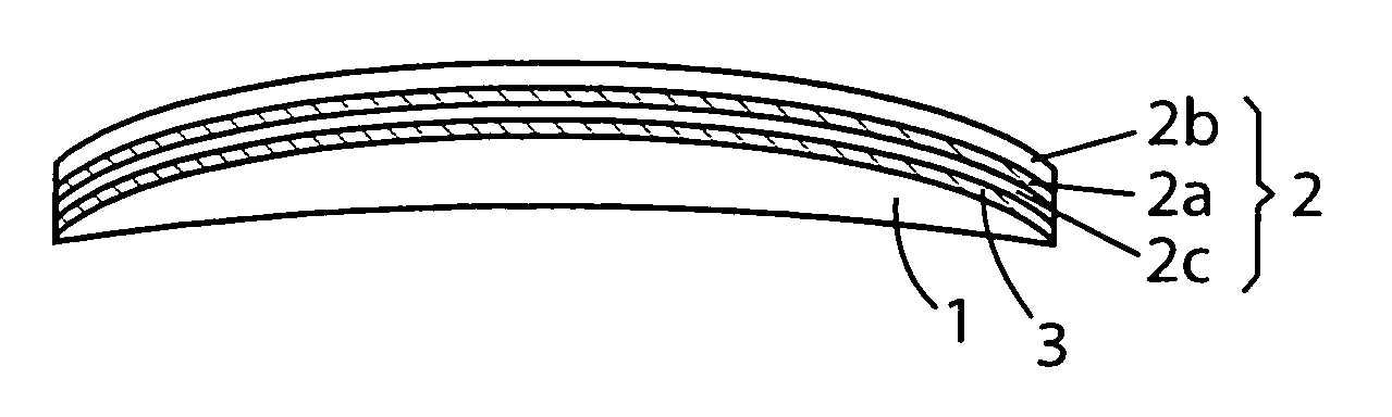
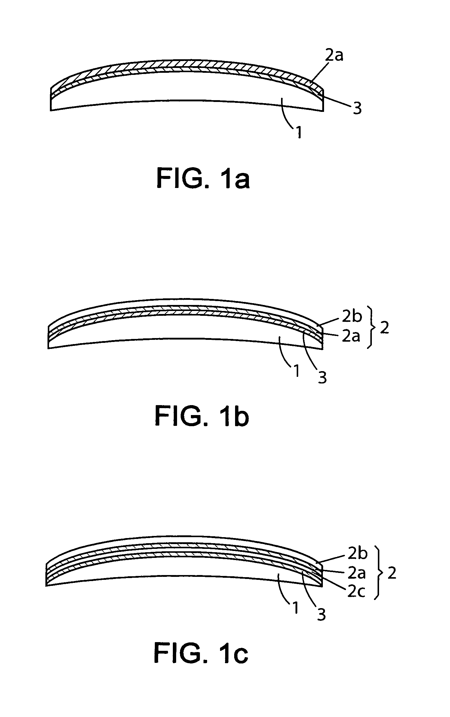
[0091] The polarizing layered structure 2 is an SHC-128UP polarizing film, of the cellulose triacetate / PVA / cellulose triacetate type, produced by Polatechno and having a total thickness of 213 microns.

[0092] This initially plane film is thermoformed and then cut into a circle in such a way that it forms part of a sphere having a curvature corresponding to 6.00 diopter base. The convex face of the film thus preformed is treated by a corona discharge.

[0093] A polythiourethane-based ophthalmic lens, of 1.665 refractive index and of 6.75 diopter base, undergoes a corona discharge treatment on its convex face.

[0094] The lens is then placed in the vacuum module of a device well known to those skilled in the art, normally used for apply...

example 2

Production of a Polarizing Ophthalmic Lens with a 1.67 Index of and a 4.0 Base

[0100] The polarizing layered structure 2 is a polarizing film of the cellulose triacetate / PVA / cellulose triacetate type produced by Nitto Denko, under the reference TEG1465DU, which includes a polyacrylate PSA layer about 20 microns in thickness. Since the polarizing layered structure 2 has a thickness of about 110 microns, the total thickness of the commercial film is about 130 microns. Two additional, flexible and removable, protective films are placed respectively on one side of the polarizing film and on the other.

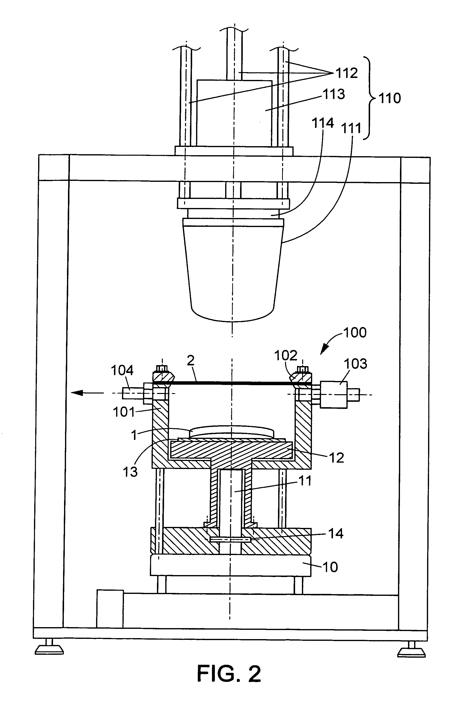
[0101] This film is initially plane. After peeling off the removable protective film located on the side with the PSA layer 3, the film is fastened to a device similar to that shown in FIG. 2, comprising a low-pressure chamber 100 and an application system 110. More precisely, the film is fastened to a chamber 100 by means of a ring 102 in such a way that the PSA layer 3 is facing the conv...


PUM

PropertyMeasurementUnit
thicknessaaaaaaaaaa
thicknessaaaaaaaaaa
thicknessaaaaaaaaaa

Abstract

A polarizing optical element comprises a transparent optical base element and a layered structure that incorporates a polarizing film. The polarizing film is of the dichroic dye type and is oriented uniaxially. The layered structure is bonded to the optical base element by means of a layered structure that includes at least one layer of a pressure-sensitive adhesive. Thanks to the use of pressure-sensitive adhesive, the polarizing film during the bonding operation maintains a high polarization efficiency and an optical quality compatible with many applications of the optical element, especially ophthalmic applications.

Description

FIELD OF THE INVENTION [0001] The present invention relates to a polarizing optical element which comprises a polarizing film based on dichroic dyes. It also relates to a method for manufacturing such a polarizing optical element. In particular, the polarizing optical element may be an ophthalmic lens. BACKGROUND OF THE INVENTION [0002] It is known to produce a polarizing optical element by combining a polarizing film based on polyvinyl alcohol or PVA with an optical base element. The optical base element is most often an optical lens. [0003] Indeed, polarizing films based on polyvinyl alcohol have been commercially available for a long time and their polarization efficiency is satisfactory. Such polarizing films are conventionally obtained by incorporating dichroic dye molecules and / or dichroic iodine crystals into a polyvinyl-alcohol-based film and then by drawing the film uniaxially so as to orient the dichroic dye molecules and / or the dichroic iodine crystals along the draw dire...

Claims


Application Information

Patent Timeline
Patent Type & Authority Applications(United States)
IPC IPC(8): G02B3/00
CPCB29C63/16B29C66/81455B29D11/00644B29D11/0073B29C66/545G02B1/08G02B5/3033B29L2011/0016B29C65/00B29K2995/007B29C66/81264B29C66/81457B29C65/10B29C65/1406B29C66/73365B29C66/7338B29C66/71B29C66/723B29K2077/00B29K2069/00B29K2067/003B29K2029/04B29K2001/14B29K2001/12G02B5/30B29D11/00G02B1/04
Inventor BEGON, CEDRICROOS, ALEXANDRA
Owner ESSILOR INT CIE GEN DOPTIQUE
Why Eureka
Try Eureka