Modular, high energy, widely-tunable ultrafast fiber source

a fiber source, high energy, widely tunable technology, applied in the direction of cladded optical fibre, instruments, active medium materials, etc., can solve the problems of limited options for wavelength tunability, inability to use such standard chirped pulse amplification systems, and inability to control the pulse shape for a further optimization of the overall system performance, etc., to achieve high peak and high average power, low noise

Inactive Publication Date: 2005-04-26
IMRA AMERICA
View PDF19 Cites 363 Cited by
  • Summary
  • Abstract
  • Description
  • Claims
  • Application Information

AI Technical Summary

Benefits of technology

[0017]Therefore, it is an object of the present invention to introduce a modular, compact, widely-tunable, high peak and high average power, low noise ultrafast fiber amplification laser system.
[0021]Further, the high energy capability of fiber amplifiers is greatly expanded by using chirped pulse amplification in conjunction with parabolic pulses or other optimized pulse shapes, which allow the toleration of large amounts of self-phase modulation without a degradation of pulse quality. Highly integrated chirped pulse amplification systems are constructed without compromising the high-energy capabilities of optical fibers by using fiber-based pulse stretchers in conjunction with bulk-optic pulse compressors (or low nonlinearity Bragg gratings) or periodically poled nonlinear crystals, which combine pulse compression with frequency-conversion.
[0023]The fiber amplifiers are seeded by short pulse laser sources, preferably in the form of short pulse fiber sources. For the case of Yb fiber amplifiers, Raman-shifted and frequency doubled short pulse Er fiber laser sources can be implemented as widely tunable seed sources. To minimize the noise of frequency conversion from the 1.5 μm to the 1.0 μm regime, self-limiting Raman-shifting of the Er fiber laser pulse source can be used. Alternatively, the noise of the nonlinear frequency conversion process can be minimized by implementing self-limiting frequency-doubling, where the center wavelength of the tuning curve of the doubling crystal is shorter than the center wavelength of the Raman-shifted pulses.
[0026]Since parabolic pulses can be transmitted along substantial fiber length, they can also be used in fiber optic communication systems. In this, parabolic pulses can be transmitted that were generated by an external pulse source. Alternatively, parabolic pulses can also be generated in the transmission process. For the latter case, the deleterious effect of optical nonlinearities in the transmission system are generally minimized by implementing long, distributed, positive dispersion optical amplifiers. Such amplifiers can have lengths of at least 10 km and a gain of less than 10 dB / km. The total gain per amplifier should exceed 10 dB, in order to exploit the onset of parabolic pulse formation for a minimization of the deleterious effect of optical nonlinearities. Chirp compensation along the transmission lines can be conveniently implemented using chirped fiber Bragg gratings along the fiber transmission line, and also at the end of the transmission line. Optical bandwidth filters can further be implemented for bandwidth control of the transmitted pulses.

Problems solved by technology

Fiber lasers have long been known to provide an effective medium for the generation of ultrashort pulses, though so far such systems have mainly been based on chirped pulse amplification using chirped Bragg gratings, with limited options for wavelength tunability and limitations in the minimal achievable pulse width (A. Galvanauskas and M. E. Fermann, ‘Optical Pulse Amplification Using Chirped Bragg Gratings,’ U.S. Pat. No. 5,499,134).
To maximize the power and energy limitations of optical fibers, the use of chirped pulse amplification is clearly desirable, though at the same time the demands for system integration (Bragg gratings need to be operated in reflection rather than in transmission to provide the highest possible dispersion) may render the use of such standard chirped pulse amplification systems impractical.
However, to date no methods for controlling the pulse-shape for a further optimization of the overall system performance have been described.
However, to date no effective methods for controlling higher-order 3rd and 4th order dispersion in such stretcher and compressor combinations for the re-compression of the pulses to near their bandwidth limit have been developed.
However, the use of this technique in conjunction with silica-based erbium amplifiers is problematic, because the requirement for positive dispersion limits the fiber core size to around 5 μm, otherwise, negative material dispersion dominates over positive waveguide dispersion, producing an overall negative fiber dispersion.
Equally, silica-based multi-mode fibers have negative dispersion at erbium amplifier wavelengths, preventing their use in efficient pulse compression.
Thus, the limited core size of positive dispersion erbium amplifiers greatly reduces the achievable pulse energy.
However, since there is no gain in such a system, high pulse energies have to be coupled into the nonlinear optical element in order to obtain a high output power, greatly reducing the peak power capability of the system.
Moreover, no means for compensating for higher-order dispersion in such an optical arrangement was discussed, greatly limiting the practicability of this approach.
In addition, without control of the pulse shape at the input to such a system, spectral broadening with a linear chirp can only be obtained for very limited input powers.
However, for high-power pulse sources, self-phase modulation introduced by a dispersion-compensating waveguide element prevents their effective use.
No means were taught for compensating for the dispersion of high-power optical pulses in the presence of self-phase modulation, and no means of implementing a dispersion-compensating waveguide without mode-converters were suggested.
However, the use of such fiber designs in high-power fiber chirped pulse amplification systems has not been discussed.
1061 (1996)), though the work by Walton et al., employed an Argon-laser pumped Ti:sapphire laser for excitation of the Yb-doped fibers as well as a modelocked Ti:sapphire laser as a source of signal pulses, which is extremely inefficient and clearly incompatible with a compact set-up.
Moreover, no means for controlling the phase of the optical pulses in the amplification process were suggested, i.e., 100 fs pulses from the Ti:sapphire laser were directly coupled to the Yb amplifier through a 1.6 km long single-mode fiber dispersive delay line, which produces large phase distortions due to higher-order dispersion, greatly limiting the applicability of the system to ultrafast applications.
The use of a single-mode Yb-doped fiber amplifier by Walton et al. further greatly limited the energy and power limits of the Yb amplifier.
Though this fiber laser offered a tuning range approximately within the gain bandwidth of Yb, application of the laser to ultrafast optics is limited due to the relatively long pulses generated by the laser.
Moreover, no method was known for minimizing the noise of such a highly nonlinear system based on the successive application of Raman shifting and nonlinear frequency conversion in a nonlinear optical crystal.
Moreover, no method was described that allowed Raman-shifting of the frequency-doubled output from an Er fiber laser.
However, to date no methods for frequency-converting such oscillators with the subsequent use of Raman-shifting have been demonstrated.

Method used


Image

  • Modular, high energy, widely-tunable ultrafast fiber source
  • Modular, high energy, widely-tunable ultrafast fiber source
  • Modular, high energy, widely-tunable ultrafast fiber source

Examples


Embodiment Construction

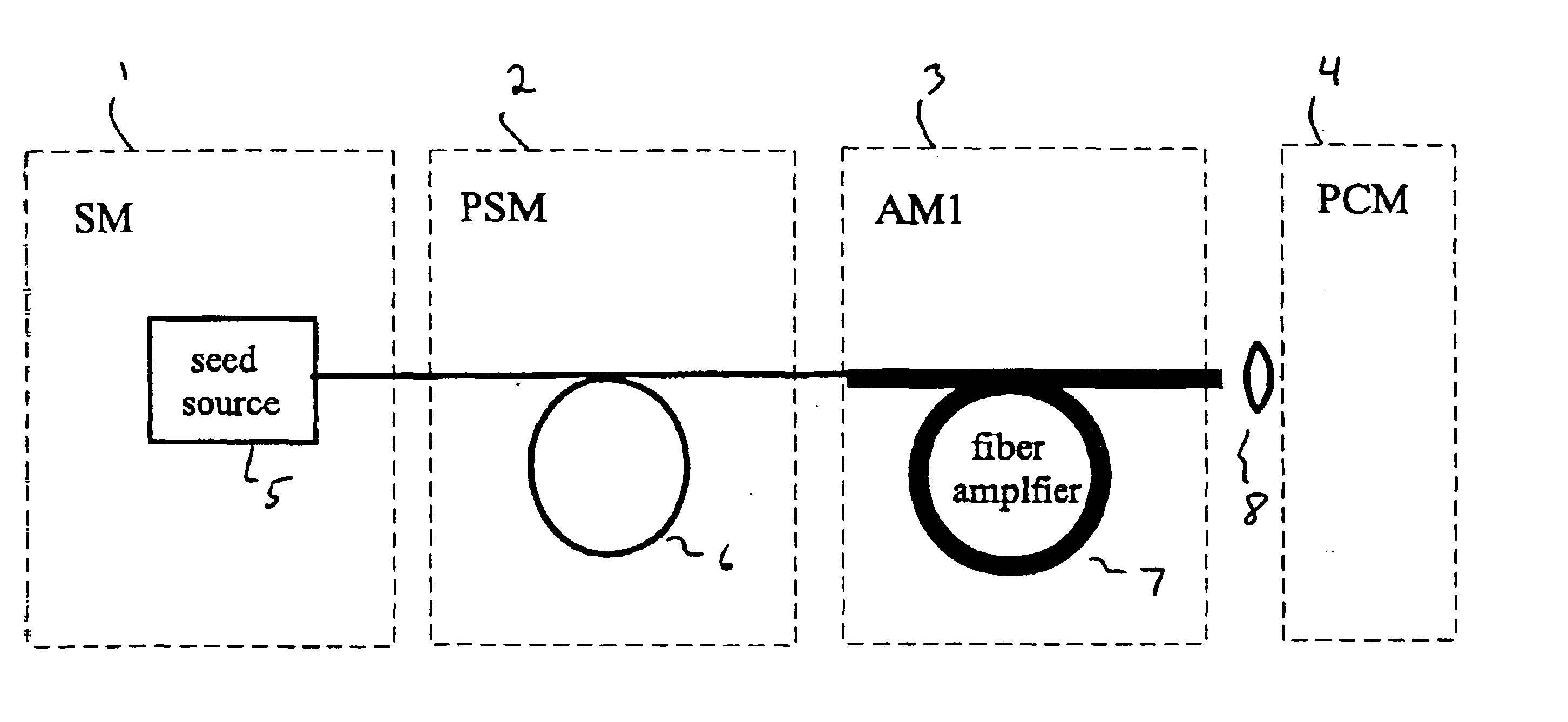
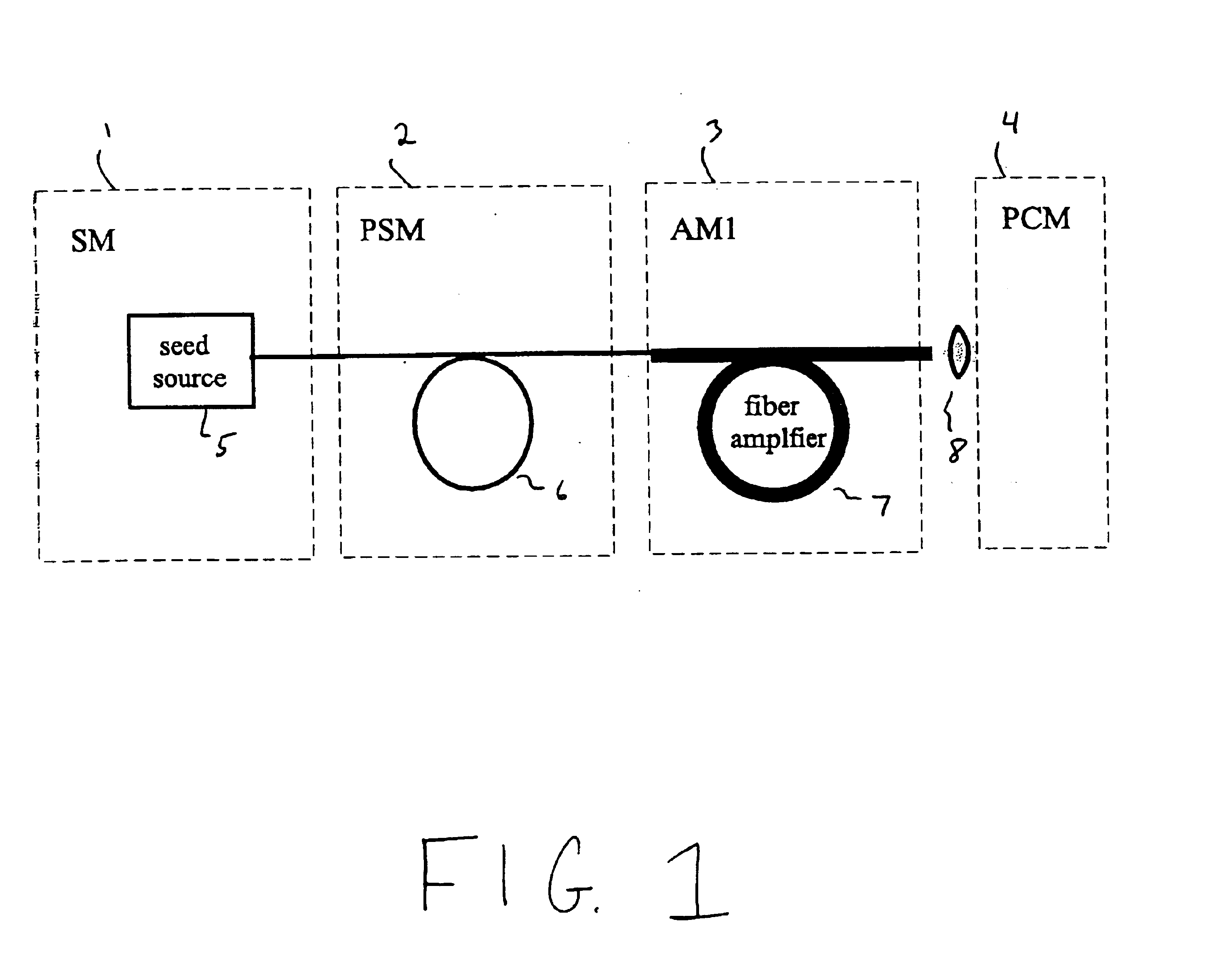
[0046]A generalized illustration of the system of the invention is shown in FIG. 1. The pulses generated in a laser seed source 1 (seed module; SM) are coupled into a pulse stretcher module 2 (PSM), where they are dispersively stretched in time. The stretched pulses are subsequently coupled into the fundamental mode of a cladding-pumped Yb fiber amplifier 3 (amplifier module, AM1), where the pulses are amplified by at least a factor of 10. Finally, the pulses are coupled into a pulse compressor module 4 (PCM), where they are temporally compressed back to approximately the bandwidth limit.

[0047]The embodiment shown in FIG. 1 is modular and consists of the four sub-systems; the SM 1, PSM 2, AM 13 and PCM 4. The sub-systems can be used independently as well as in different configurations, as described in the alternative embodiments.

[0048]In the following, discussion is restricted to the SM-PSM-AM1-PCM system. The SM 1 preferably comprises a femtosecond pulse source (seed source 5). The...


PUM

PropertyMeasurementUnit
wavelengthaaaaaaaaaa
wavelength rangeaaaaaaaaaa

Abstract

A modular, compact and widely tunable laser system for the efficient generation of high peak and high average power ultrashort pulses. Modularity is ensured by the implementation of interchangeable amplifier components. System compactness is ensured by employing efficient fiber amplifiers, directly or indirectly pumped by diode lasers. Peak power handling capability of the fiber amplifiers is expanded by using optimized pulse shapes, as well as dispersively broadened pulses. After amplification, the dispersively stretched pulses can be re-compressed to nearly their bandwidth limit by the implementation of another set of dispersive delay lines. To ensure a wide tunability of the whole system, Raman-shifting of the compact sources of the ultrashort pulses in conjunction with frequency-conversion in nonlinear optical crystals can be implemented, or an Anti-Stokes fiber in conjunction with fiber amplifiers and Raman-shifters are used.

Description

BACKGROUND OF THE INVENTION[0001]1. Field of the Invention[0002]This invention relates to wavelength-tunable, compact, modular and efficient sources of high-power ultrashort laser pulses, which are an essential ingredient in the commercial use of ultrafast laser technology.[0003]2. Description of the Related Art[0004]Fiber lasers have long been known to provide an effective medium for the generation of ultrashort pulses, though so far such systems have mainly been based on chirped pulse amplification using chirped Bragg gratings, with limited options for wavelength tunability and limitations in the minimal achievable pulse width (A. Galvanauskas and M. E. Fermann, ‘Optical Pulse Amplification Using Chirped Bragg Gratings,’ U.S. Pat. No. 5,499,134). Chirped Bragg gratings have indeed been developed into widely available devices, and the chirp inside the Bragg gratings can be designed to be linear or even nonlinear to compensate any order of dispersion in a chirped pulse amplification...

Claims


Application Information

Patent Timeline
Patent Type & Authority Patents(United States)
IPC IPC(8): H01S3/06H01S3/067H01S3/23H01S3/16H01S3/094H01S3/109H01S3/00G02F1/35G02F1/37G02B6/02H01S3/10H01S3/30
CPCH01S3/06754H01S3/1115H01S3/1112H01S3/302H01S3/0057H01S3/0675H01S3/094019H01S3/094042H01S3/1616H01S3/1618H01S3/109
Inventor FERMANN, MARTIN E.GALVANAUSKAS, ALMANTASHARTER, DONALD J.
Owner IMRA AMERICA
Why Eureka
Try Eureka