Large building deformation monitoring device and monitoring method through large building deformation monitoring device

A deformation monitoring and building technology, applied in the direction of measuring devices, optical devices, instruments, etc., can solve the problems of long-term retention, large manpower and material resources, and inability to build, and achieves small divergence, convenient installation, and good linearity Effect

Inactive Publication Date: 2013-05-15
TANGSHAN COLLEGE
View PDF5 Cites 25 Cited by
  • Summary
  • Abstract
  • Description
  • Claims
  • Application Information

AI Technical Summary

Problems solved by technology

[0003] The purpose of the invention of the present invention is that the displacement sensor in the prior art must be installed on a reference position that is perpendicular to the deformation surface of the measured object and relatively close to the measured object. Establishing this reference position requires a lot of manpower and material resources. It cannot be kept for a long time; sometimes it cannot be established at all. One is to provide a large-scale building deformation monitoring device with a laser transmitter and a laser receiver as the main body, and the other is to provide a large-scale building deformation monitoring device for monitoring large-scale The method of building deformation, using this device to monitor does not need to establish a measuring point on a reference point perpendicular to the deformation surface of the measured object, and can directly measure the deformation of the measured object, suitable for large-scale building performance testing, and can also be used for long-term safety monitoring A large-scale building deformation monitoring device and a monitoring method thereof, the method overcomes many defects of the prior art and solves the above-mentioned problems existing in the prior art

Method used


Image

  • Large building deformation monitoring device and monitoring method through large building deformation monitoring device
  • Large building deformation monitoring device and monitoring method through large building deformation monitoring device
  • Large building deformation monitoring device and monitoring method through large building deformation monitoring device

Examples


Embodiment 1

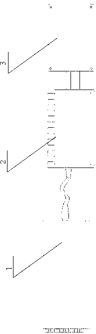
[0027] A large-scale building deformation monitoring device, the device consists of a laser collimator 1, a laser power supply 2, a laser controller 3, a semi-transparent laser target 4, a light shield 5, an image sensor 6, an attitude sensor 7, a microprocessor 9, Wireless transmitter 8 and wireless receiver 15.

[0028] See figure 1 , the input end of the laser controller 1 of model LC100 is connected with the laser power supply 2 of model FCM635S5L, and the output end of laser power supply 2 is connected with the laser collimator 1 of model 70-200RV to form a laser emitter 13.

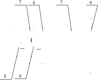
[0029] See figure 2 , semi-transparent laser target 4, hood 5, image sensor 6, attitude sensor 7, microprocessor 9 and wireless transmitter 8 constitute a laser receiver 11. The semi-transparent laser target 4 made of frosted glass with a thickness of 3 mm is glued and connected with the light hood 5 made of aluminum alloy. The light hood 5 is screwed with the image sensor 6 of the model AXB-133...

Embodiment 2

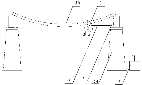
[0034] The method of monitoring the deformed surface of bridges with large-scale building deformation monitoring devices can be found in image 3 .

[0035] The laser emitter 13 is installed on a relatively fixed reference point close to the measured object, and emits a beam of laser light 12 parallel to the deformation surface of the measured object. The laser receiver 11 is placed under the bridge deck and opposite to the laser transmitter 13, and is installed on the measured point of the deformed surface. The target surface of the semi-transparent laser target 4 is perpendicular to the measured deformed surface 10. A spot of light is generated on the laser target 4 . The spot position before the test is determined as the reference position, and the angle of the laser receiver 11 is the reference angle. When the measured deformation surface 10 is deformed, the position and angle of the laser receiver 11 also change accordingly. The linear displacement value of the light s...


PUM


Abstract

The invention discloses a large building deformation monitoring device and a monitoring method through the large building deformation monitoring device. A laser transmitter of the large building deformation monitoring device is composed of a laser controller, a laser power supply and a laser collimator, wherein the laser controller is connected with the laser power supply, and the laser power supply is connected with the laser collimator. A laser receiver is composed of a semi-permeable laser target, a light shield, an image sensor, and an attitude sensor, wherein the semi-permeable laser target is connected with the light shield, the light shield is connected with the image sensor, and the image sensor, the attitude sensor and a wireless transmitter are respectively connected with a microprocessor, and therefore the large building deformation monitoring device is formed. The method monitoring method through the large building deformation monitoring device includes that the laser transmitter is mounted at a reference position which is close to an object to be tested and is relatively fixed; the laser receiver is mounted at a point to be tested on a deformation surface; and the linear displacement, perpendicular to the deformation surface, of the laser receiver is the deformation value of the point. According to the large building deformation monitoring device, laser is utilized for testing deformation, and therefore the large building deformation monitoring device is convenient to install and test, high in accuracy, and suitable for long-time on-line monitoring of the deformation of large buildings.

Description

technical field [0001] The invention relates to a building deformation monitoring device and a monitoring method, in particular to a large building deformation monitoring device for real-time online deformation monitoring of a large building and a monitoring method using the same. Background technique [0002] When performing performance testing on large buildings such as houses, bridges, and dams, it is usually necessary to measure the shape changes of their important parts; these buildings will also be deformed due to changes in natural conditions and loads exceeding the limit during use, and the deformation will exceed a certain limit. cause havoc. Therefore, the deformation monitoring of large buildings is very important to ensure its safe use. At present, the monitoring of deformation is mainly the method of using displacement sensor and the indirect measurement method of calculating deformation by measuring strain. Use a displacement sensor to understand the deformat...

Claims


Application Information

Patent Timeline
Patent Type & Authority Applications(China)
IPC IPC(8): G01B11/16
CPCG01B11/16G01B11/26
Inventor 赵晨光雷振山
Owner TANGSHAN COLLEGE
Why Eureka
Try Eureka