A centrifugal force pendulum with a damper

A technology of centrifugal force pendulum and pendulum flange, applied in the field of centrifugal force pendulum, can solve the problem of reducing the swing stroke, and achieve the effect of reducing the risk of breaking, simple and effective vibration reduction

Active Publication Date: 2013-06-12
SCHAEFFLER TECH AG & CO KG
View PDF6 Cites 14 Cited by
  • Summary
  • Abstract
  • Description
  • Claims
  • Application Information

AI Technical Summary

Problems solved by technology

Furthermore, the known prior art has the disadvantage that the pivoting stroke of the pendulum mass relative to the pendulum flange is reduced due to the elastic element

Method used


Image

  • A centrifugal force pendulum with a damper
  • A centrifugal force pendulum with a damper
  • A centrifugal force pendulum with a damper

Examples


Embodiment Construction

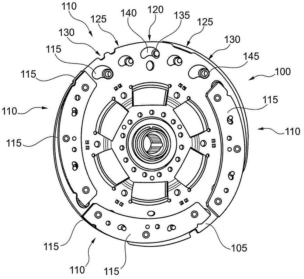
[0023] figure 1 A mass damper with a centrifugal pendulum 100 is shown. The centrifugal pendulum 100 includes a pendulum flange 105 which is arranged rotatably about an axis which transmits torque in a drive train. The drive train may include, inter alia, the drive motor and the transmission of the vehicle. Centrifugal force pendulum 100 also comprises four pendulum masses 110, in figure 1 Only three of them are fully shown in . Each pendulum mass 110 includes two mass elements 115 which are situated on different axial sides of the pendulum flange 105 . On the upper pendulum mass 110 , the mass element 115 facing the observer has been removed for a clearer illustration.

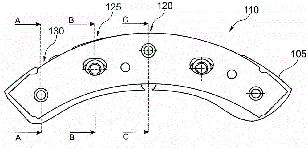
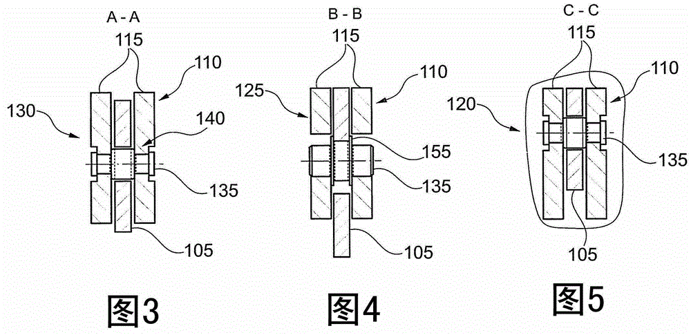
[0024] The mass elements 115 of each pendulum mass 110 are fixed on the pendulum flange 105 by means of a central link guide 120 , two inner link guides 125 and two outer link guides 130 in such a way that the pendulum masses 110 can Pivots in the plane of rotation of the pendulum flange 105 . Each link...


PUM


Abstract

The invention relates to a centrifugal force pendulum, specifically to a centrifugal force pendulum in a torsional vibration absorber of a motor vehicle power train. The centrifugal force pendulum comprises a pendulum flange and a pendulum weight. The pendulum weight comprises two weight elements which are disposed on the different axial sides of the pendulum flange and are connected with each other via a pin. The pin extends after passing through an opening in the pendulum flange and forms a chute guide device together with the opening for limiting pendulosity of the pendulum weight relative to the pendulum flange. Elastic elements are arranged between the radial surface of the pin and the weight elements for vibration damping of the weight elements when the pin is stopped at the edge of the opening.

Description

technical field [0001] The invention relates to a centrifugal force pendulum. In particular, the invention relates to a spring element for damping a pendulum mass when it is abutted against a pendulum flange of a centrifugal pendulum. Background technique [0002] Torsional vibration dampers are used in the drive train of a motor vehicle to damp torsional vibrations which may be caused, inter alia, by uneven torque variations of the drive motor. In particular, the torsional vibration damper can be arranged between the drive motor and the transmission. [0003] To counteract torsional vibrations, the torsional vibration damper comprises a centrifugal pendulum comprising a pendulum flange and at least one pendulum mass, which is pivotable relative to the pendulum flange in a plane of rotation. In certain operating states of the drive train, for example when the drive motor is at a standstill or when changing gears, the pendulum mass can be accelerated so strongly that it hit...

Claims


Application Information

Patent Timeline
Patent Type & Authority Applications(China)
IPC IPC(8): F16F15/14
CPCF16F15/145
Inventor F·巴拉尔D·施纳德尔巴赫
Owner SCHAEFFLER TECH AG & CO KG
Why Eureka
Try Eureka