Non-destructive disassembly device for compressor rotor shrink sleeve assembly

A compressor rotor and heating device technology, which is applied in metal processing, metal processing equipment, manufacturing tools, etc., can solve the problem of rotor aluminum end ring, crankshaft long shaft crankcase deformation damage due to force, rotor aluminum leakage and deformation, interference If there are problems such as large matching amount, it can achieve the effect of uniform heating, reducing ejection force and reducing interference.

Active Publication Date: 2016-01-20
SICHUAN CHANGHONG ELECTRIC CO LTD
View PDF5 Cites 2 Cited by
  • Summary
  • Abstract
  • Description
  • Claims
  • Application Information

AI Technical Summary

Problems solved by technology

The fire method is to directly heat the rotor of the motor to about 250°C, so that the diameter of the inner hole of the rotor increases to form a gap with the mating crankshaft and separates. This method consumes a lot of energy, and the disassembly efficiency is low. Cause damage such as rotor aluminum leakage and deformation; the pressure unloading method is to use a pressure tool to press the crankshaft out of the rotor. Defects such as roughening of the surface of the crankshaft, damage to the aluminum end ring of the rotor, the long axis of the crankshaft and the crankcase, etc.

Method used


Image

  • Non-destructive disassembly device for compressor rotor shrink sleeve assembly
  • Non-destructive disassembly device for compressor rotor shrink sleeve assembly
  • Non-destructive disassembly device for compressor rotor shrink sleeve assembly

Examples


Embodiment Construction

[0023] The present invention will be further described below in combination with specific embodiments and accompanying drawings.

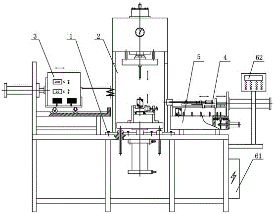
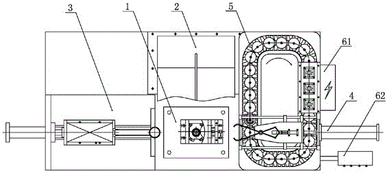
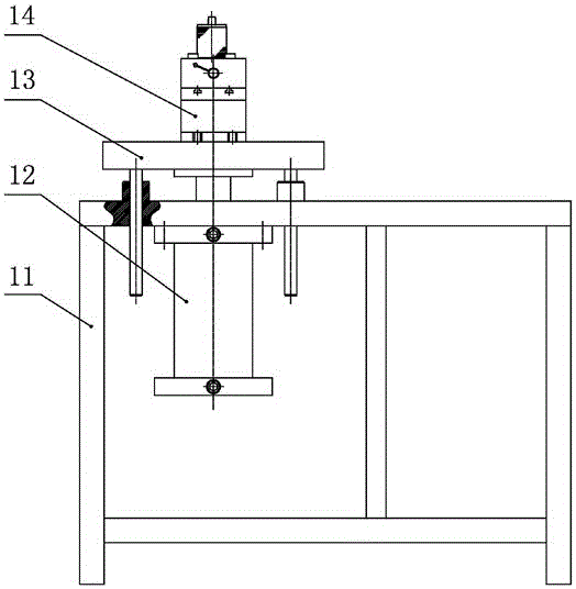
[0024] Such as figure 1 with figure 2 As shown, a non-destructive disassembly device for a compressor rotor shrink sleeve assembly, including a frame, and a jacking mechanism 1 installed on the frame, a hydraulic ejection mechanism 2, a high-frequency heating device 3, a rotor transfer mechanism 4, and a rotor Cooling mechanism 5 and control mechanism 6. The top of the jacking mechanism 1 is provided with a clamping fixture 14; the high-frequency heating device 3 is arranged on the upper left part of the jacking mechanism 1, which can move left and right and heat the workpiece; the hydraulic ejector mechanism 2 is arranged on the jacking mechanism 1 and the high-frequency heating Above the device 3, its pressure center coincides with the center of the jacking mechanism 1; the rotor transfer mechanism 4 is arranged on the upper right part of the ...


PUM


Abstract

The invention discloses a damage-free compressor rotor heat jacket assembly disassembling device. The damage-free compressor rotor heat jacket assembly disassembling device is provided with a jacking mechanism which is capable of lifting vertically, a clamp jig capable of clamping a workpiece is arranged at the top of the jacking mechanism, a high frequency heating device used for heating the workpiece and capable of moving leftwards and rightwards is mounted on the upper left portion of the jacking mechanism, a hydraulic ejection mechanism capable of ejecting out a crankshaft is mounted above the jacking mechanism and the high-frequency heating device, a pressure center of the hydraulic ejection mechanism is coincided with the center of the jacking mechanism, a rotor shifting mechanism capable of clamping a rotor to move leftwards and rightwards is mounted on the upper right portion of the jacking mechanism and below the hydraulic ejection mechanism, a rotor cooling mechanism capable of cooling a rotor shifted from the rotor shifting mechanism is mounted below the rotor shifting mechanism, and the jacking mechanism, the high-frequency heating device, the hydraulic ejection mechanism, the rotor shifting mechanism and the rotor cooling mechanism are connected with a controlling mechanism. The damage-free compressor rotor heat jacket assembly disassembling device has the advantages of simplicity in operation, high disassembling efficiency, small damage to disassembled parts, and good reusability.

Description

technical field [0001] The invention belongs to the technical field of dismantling equipment for a compressor rotor thermal sleeve assembly, in particular to a non-destructive disassembly device for a compressor rotor thermal sleeve assembly. Background technique [0002] The motor rotor and crankshaft in the compressor are usually assembled into a rotor shrink-fit assembly by interference fit, which is difficult to disassemble, and may easily cause damage to the rotor or crankshaft during disassembly. At present, the disassembly methods of the compressor rotor shrink sleeve assembly are mainly the fire method and the pressure unloading method. The fire method is to directly heat the rotor of the motor to about 250°C, so that the diameter of the inner hole of the rotor increases to form a gap with the mating crankshaft and separates. This method consumes a lot of energy, and the disassembly efficiency is low. Cause damage such as rotor aluminum leakage and deformation; the ...

Claims


Application Information

Patent Timeline
Patent Type & Authority Patents(China)
IPC IPC(8): B23P11/02
Inventor 潘晓勇韦泽平彭玲汪年结陈正陈伟华刘宇
Owner SICHUAN CHANGHONG ELECTRIC CO LTD
Why Eureka
Try Eureka