An antenna arrangement

A technology of antenna device and locking device, which is applied in the direction of antenna, antenna coupling, antenna array, etc., can solve the problem of reducing capacity and achieve the effect of improving link gain and equalizing radiation performance

Active Publication Date: 2013-07-24
TELEFON AB LM ERICSSON (PUBL)
View PDF4 Cites 5 Cited by
  • Summary
  • Abstract
  • Description
  • Claims
  • Application Information

AI Technical Summary

Problems solved by technology

Power imbalance is a problem eg in MIMO multi-stream transmission which results in reduced capacity

Method used


Image

  • An antenna arrangement
  • An antenna arrangement
  • An antenna arrangement

Examples


Embodiment 100

[0031] The radiating elements of embodiment 100 are elongated slots in the outer conductors 114, 124 that are perforated through, and have a main direction of elongation that causes the slots to radiate. The main direction of extension in which the slots radiate differs between different types of cables: in coaxial cables, as shown in the figure, the main direction of extension should not coincide with the main extension length of the cable. In waveguide, or microstrip, or stripline structures, the main direction of elongation of the slots can coincide with that of the structure or cable and still radiate. Regarding the precise shape of the radiating elements, it should be noted that although in the figures they are shown as elongated slots and are referred to as such in the description, the radiating elements can be chosen from a number of different types of perforations in the outer conductor shape, although preferred embodiments comprise elongated rectangular or oval slots....

Embodiment 200

[0035] The radiating element of embodiment 200 is also an elongated slot in the outer conductor 214 , 224 , 234 , 244 through the perforation and has a main direction of elongation that causes the slot to radiate. Preferably, the shape and distribution of the perforations of all cables are approximately equal.

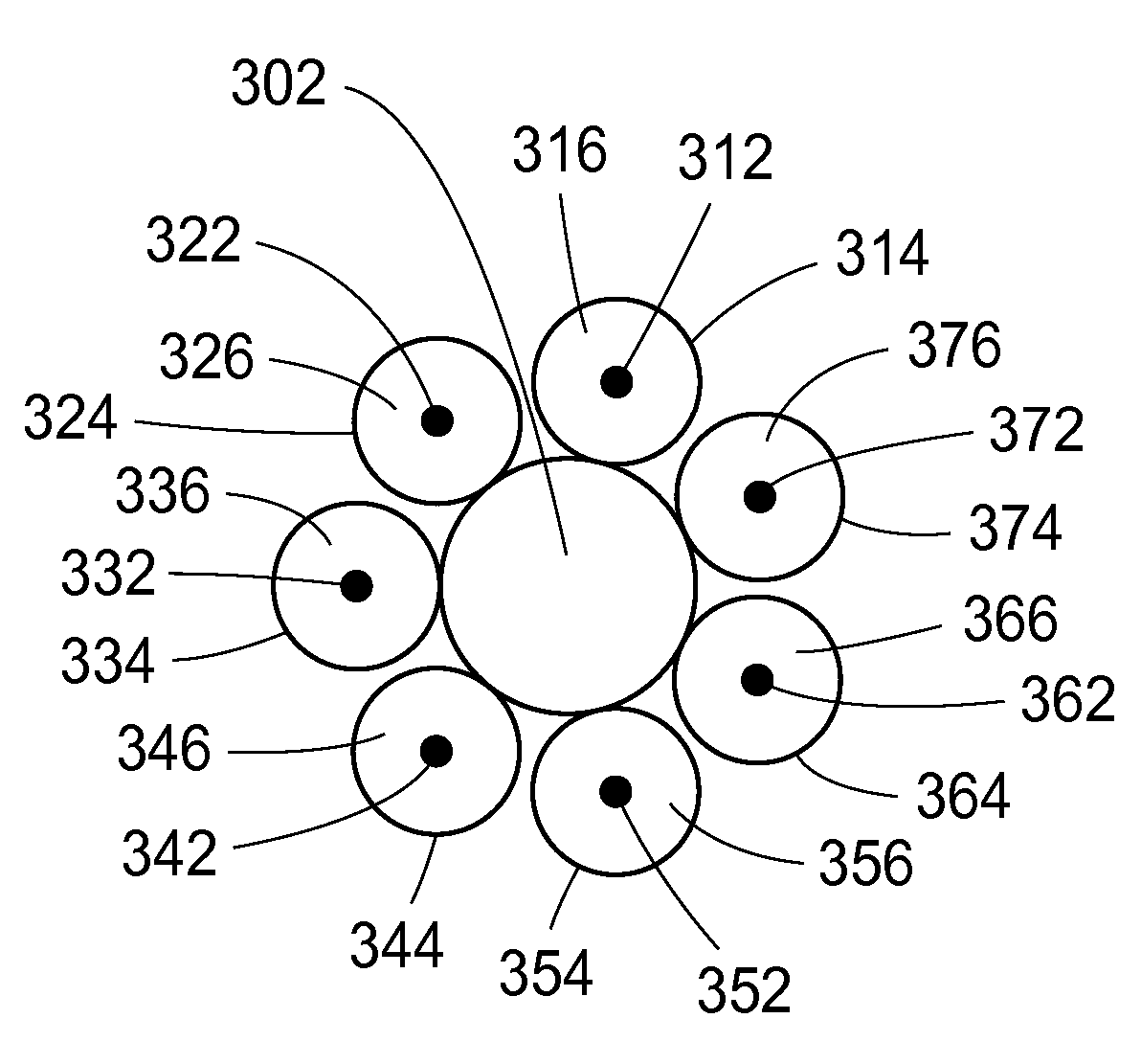
[0036]Furthermore, as shown in Fig. 3a, the cables 210, 220, 230, 240 are arranged within the bundle such that the radial positions of the cables 210, 220, 230, 240 alternate in the direction of longitudinal extension. The alternation of the radial positions of the cables 210, 220, 230, 240 may be formed by folding at least one cable present at a first side of the bundle to a second side of the bundle. Thus, by periodically changing the location of each cable 210, 220, 230, 240 in the section of the bundle, at all locations along the extension of the bundle, the occurrence of all cables 210, 220, 230, 240 is equal. Furthermore, the alternation of the radial positions...


PUM


Abstract

An antenna arrangement comprising at least a first and a second elongated structure, e.g., a coaxial cable, for guiding an electromagnetic wave is provided. Each of said structures comprises a plurality of radiation elements. The structures are positioned alongside each other in their longitudinal direction of extension forming a bundle. The elongated structures are arranged within the bundle such that the radial positions of said structures are alternated in the longitudinal direction of extension.

Description

technical field [0001] The invention discloses a novel antenna device. Background technique [0002] In general, conventional types of antennas may not be suitable for use when deploying wireless communication systems (eg, cellular systems) in indoor environments. In such environments, use sometimes instead consists of so-called "leaky cables" (also sometimes called leaky feeders or radiating cables). [0003] A leaky cable is a cable that is capable of conducting electromagnetic radio frequency energy and that has been equipped with slots to allow the cable to radiate (ie, allow some energy to "leak" from the cable), thus enabling the cable to function as an antenna. Such an antenna (ie a leaky cable) would be able to function equally well as a receiving antenna and a transmitting antenna because of reciprocity. Due to its cable nature, a "leaky cable antenna" will behave more like a line source than a point source compared to a conventional antenna, thus making it easier...

Claims


Application Information

Patent Timeline
Patent Type & Authority Applications(China)
IPC IPC(8): H01Q1/00H01Q1/52H01Q13/20H01Q21/20H01Q21/28H01Q13/22
CPCH01Q1/007H01Q21/28H01Q21/205H01Q13/203H01Q13/22H01Q1/521
Inventor H.阿斯普伦A.德纳伊德J.梅德博
Owner TELEFON AB LM ERICSSON (PUBL)
Why Eureka
Try Eureka