An antenna arrangement
A technology of an antenna device and a locking device, which is applied in directions such as antennas, antenna couplings, and antenna arrays, can solve problems such as reducing capacity, and achieve the effects of improving link gain and balancing radiation performance.
- Summary
- Abstract
- Description
- Claims
- Application Information
AI Technical Summary
Problems solved by technology
Method used
Image
Examples
Embodiment 100
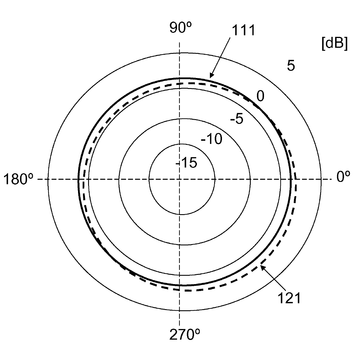
[0031] The radiating elements of embodiment 100 are elongated slots in the outer conductors 114, 124 that are perforated through, and have a main direction of elongation that causes the slots to radiate. The main direction of extension in which the slots radiate differs between different types of cables: in coaxial cables, as shown in the figure, the main direction of extension should not coincide with the main extension length of the cable. In waveguide, or microstrip, or stripline structures, the main direction of elongation of the slots can coincide with that of the structure or cable and still radiate. Regarding the precise shape of the radiating elements, it should be noted that although in the figures they are shown as elongated slots and are referred to as such in the description, the radiating elements can be chosen from a number of different types of perforations in the outer conductor shape, although preferred embodiments comprise elongated rectangular or oval slots....
Embodiment 200
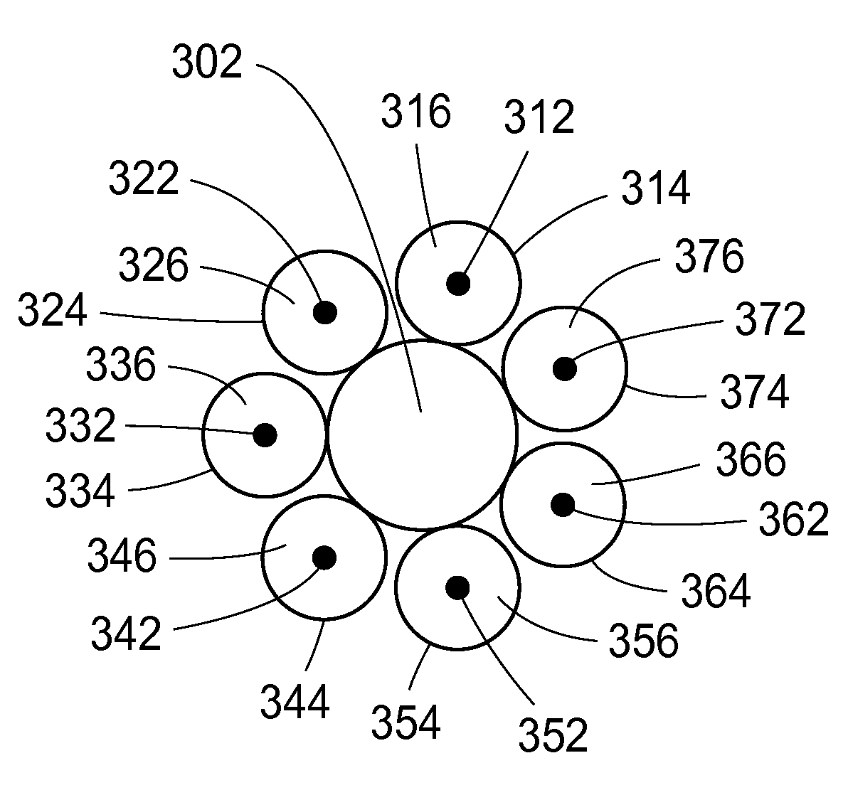
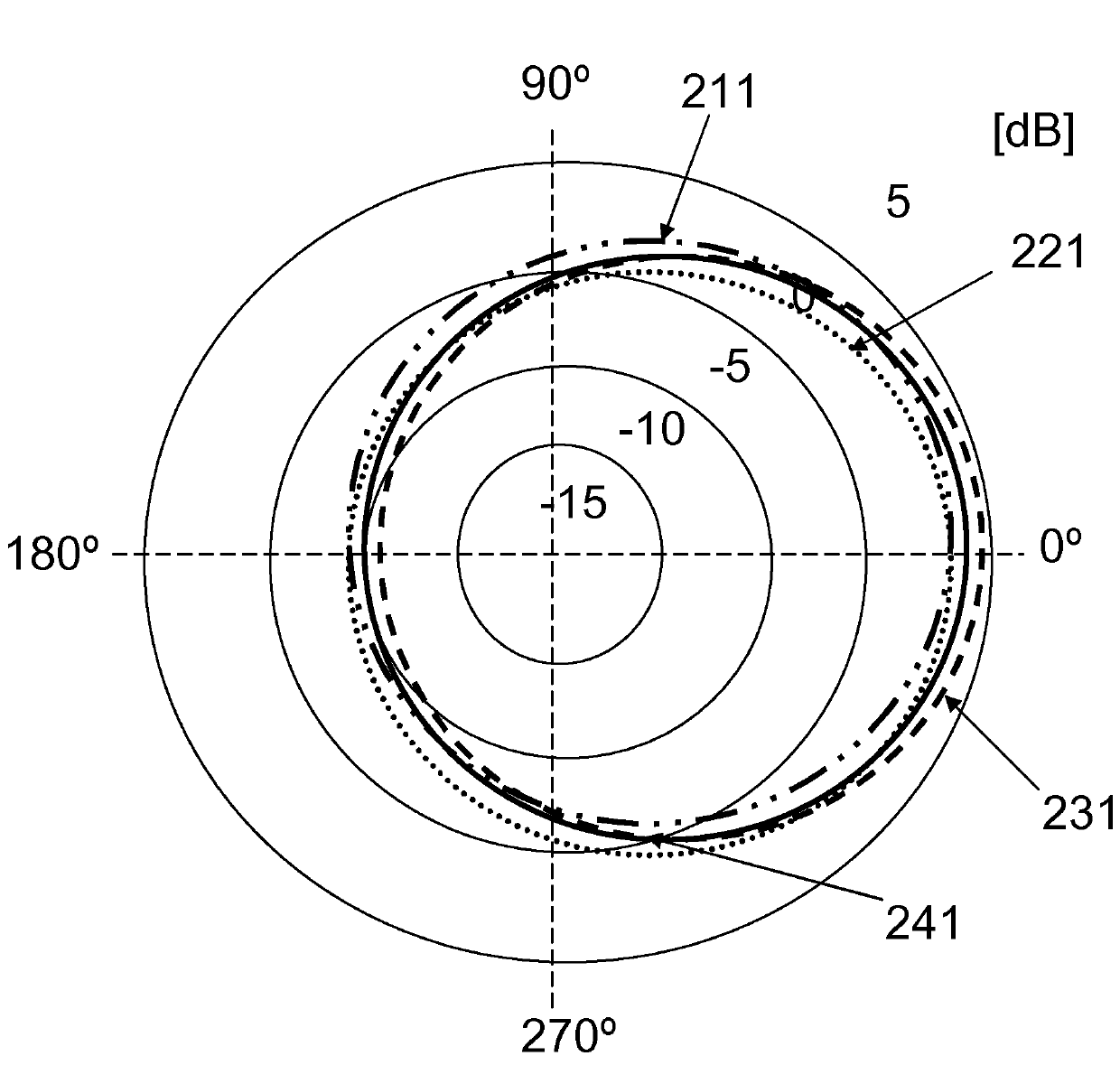
[0035] The radiating element of embodiment 200 is also an elongated slot in the outer conductor 214 , 224 , 234 , 244 through the perforation and has a main direction of elongation that causes the slot to radiate. Preferably, the shape and distribution of the perforations of all cables are approximately equal.
[0036] Additionally, as in Figure 3a As shown in , the cables 210, 220, 230, 240 are arranged within the bundle such that the radial positions of the cables 210, 220, 230, 240 alternate in the direction of longitudinal extension. The alternation of the radial positions of the cables 210, 220, 230, 240 may be formed by folding at least one cable present at a first side of the bundle to a second side of the bundle. Thus, by periodically changing the location of each cable 210, 220, 230, 240 in the section of the bundle, at all locations along the extension of the bundle, the occurrence of all cables 210, 220, 230, 240 is equal. Furthermore, the alternation of the r...
PUM
 Abstract
Description
Claims
Application Information
 - R&D
- Intellectual Property
- Life Sciences
- Materials
- Tech Scout
- Unparalleled Data Quality
- Higher Quality Content
- 60% Fewer Hallucinations
Browse by: Latest US Patents, China's latest patents, Technical Efficacy Thesaurus, Application Domain, Technology Topic, Popular Technical Reports.
© 2025 PatSnap. All rights reserved.Legal|Privacy policy|Modern Slavery Act Transparency Statement|Sitemap|About US| Contact US: help@patsnap.com


