Full-automatic numerically-controlled machine tool for shafts

A CNC machine tool, fully automatic technology, applied in the field of machinery, can solve the problems of increasing the moving distance of the ejector rod, reducing work efficiency, and inaccurate positioning, so as to achieve the effect of shortening the moving distance, improving work efficiency, and avoiding inaccurate positioning

Active Publication Date: 2013-09-04
宁波宫铁智能科技有限公司
View PDF7 Cites 19 Cited by
  • Summary
  • Abstract
  • Description
  • Claims
  • Application Information

AI Technical Summary

Problems solved by technology

Although this structure realizes the bar material automatic conveying function, there are still some problems as follows: 1. After the bar material slides from the material box to the conveying channel, the bar is pushed into the main machine by the push rod and is set on the The stopper device in front of the main machine can only be clamped by the chuck of the main machine. In this process, the ejector rod is always on the rear end of the bar and goes through the entire stroke, which causes the problem of low efficiency; 2. In the process of clamping When it is tightened to the critical state, because the ejector rod is slender, it is easy to bend, and the degree of bending is different each time, resulting in inaccurate positioning; During the tightening process, the ejector rod needs to be pushed against the rear end of the bar, so the thrust of the ejector rod must be greater than the back thrust generated when the chuck of the main machine is clamped, so the requirements for the cylinder that controls the movement of the ejector rod are higher, which increases production. Cost; 4. After the shaft is processed, the ejector rod needs to continue to move forward to move the shaft out from the main shaft and fall onto the blanking plate, so that the ejector rod can only be pushed forward once to complete the feeding or blanking process, that is The two processes of feeding and blanking can only be performed separately, which increases the moving distance of the ejector rod and reduces the work efficiency

Method used


Image

  • Full-automatic numerically-controlled machine tool for shafts
  • Full-automatic numerically-controlled machine tool for shafts
  • Full-automatic numerically-controlled machine tool for shafts

Examples


Embodiment 1

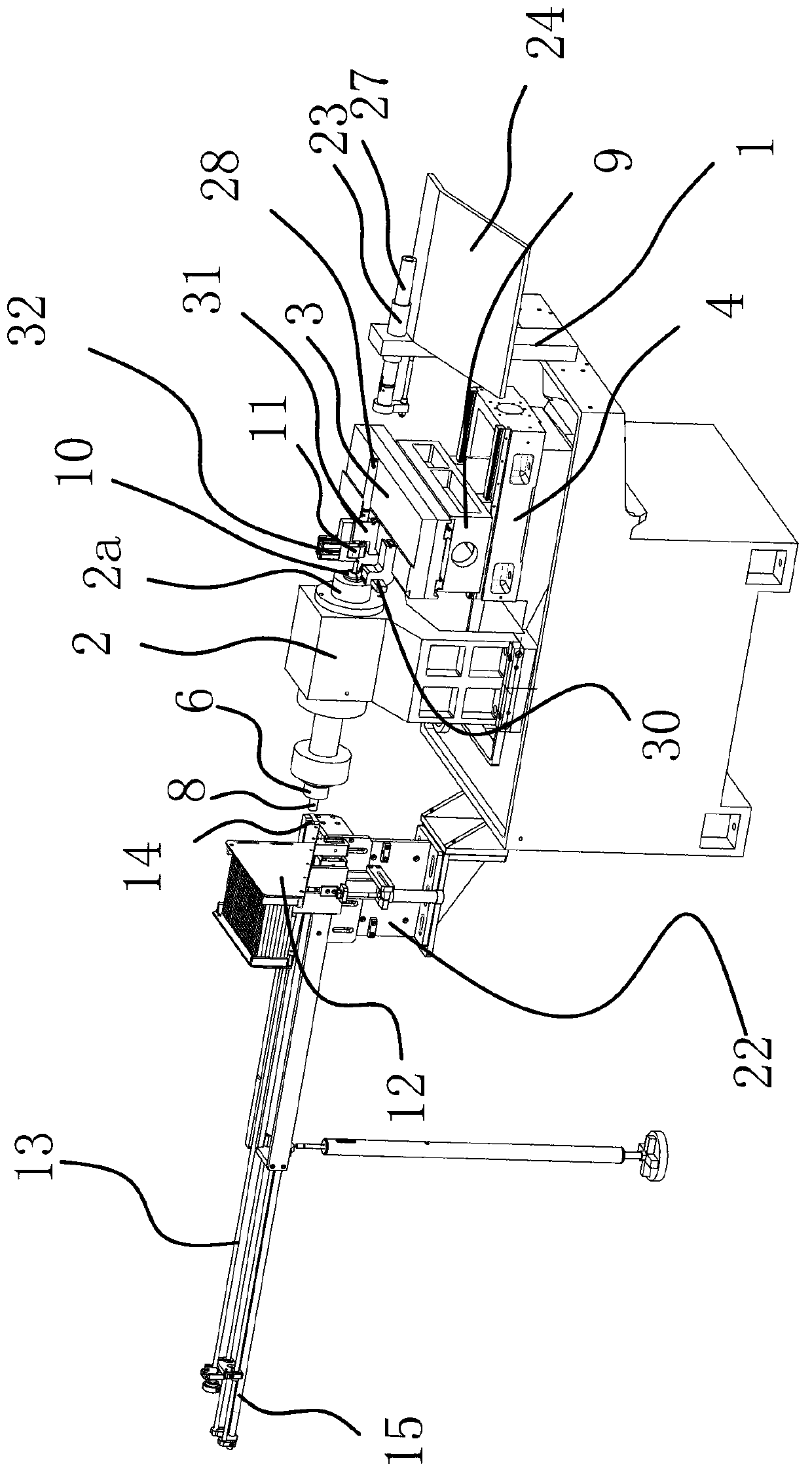
[0029] Such as figure 1 As mentioned above, this axis type fully automatic CNC machine tool includes a main frame 2 for processing shafts and having a main shaft 2a, and a front frame 22 and a rear frame 1 respectively arranged on both sides of the main frame 2 .

[0030] Front frame 22 upper side parts are equipped with and are used to place axle and the material box 12 that tilts to arrange, there is material delivery channel 14 on the front frame 22 and material box 12 outlets are communicated with material delivery channel 14, and there is delivery channel 14 on the front frame 22. The material channel 14 and the outlet of the material box 12 communicate with the material delivery channel 14, the outlet of the material box 12 communicates with the material delivery channel 14 and the height of the outlet of the material box 12 is slightly greater than the diameter of the shaft, which can ensure that the shaft enters the material delivery channel When inside 14, go in alone, ...

Embodiment 2

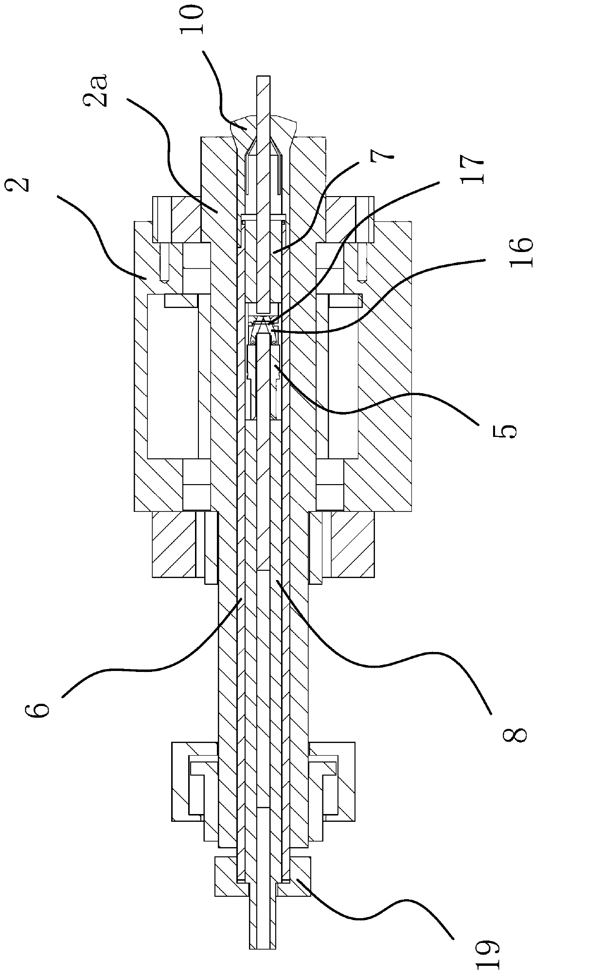
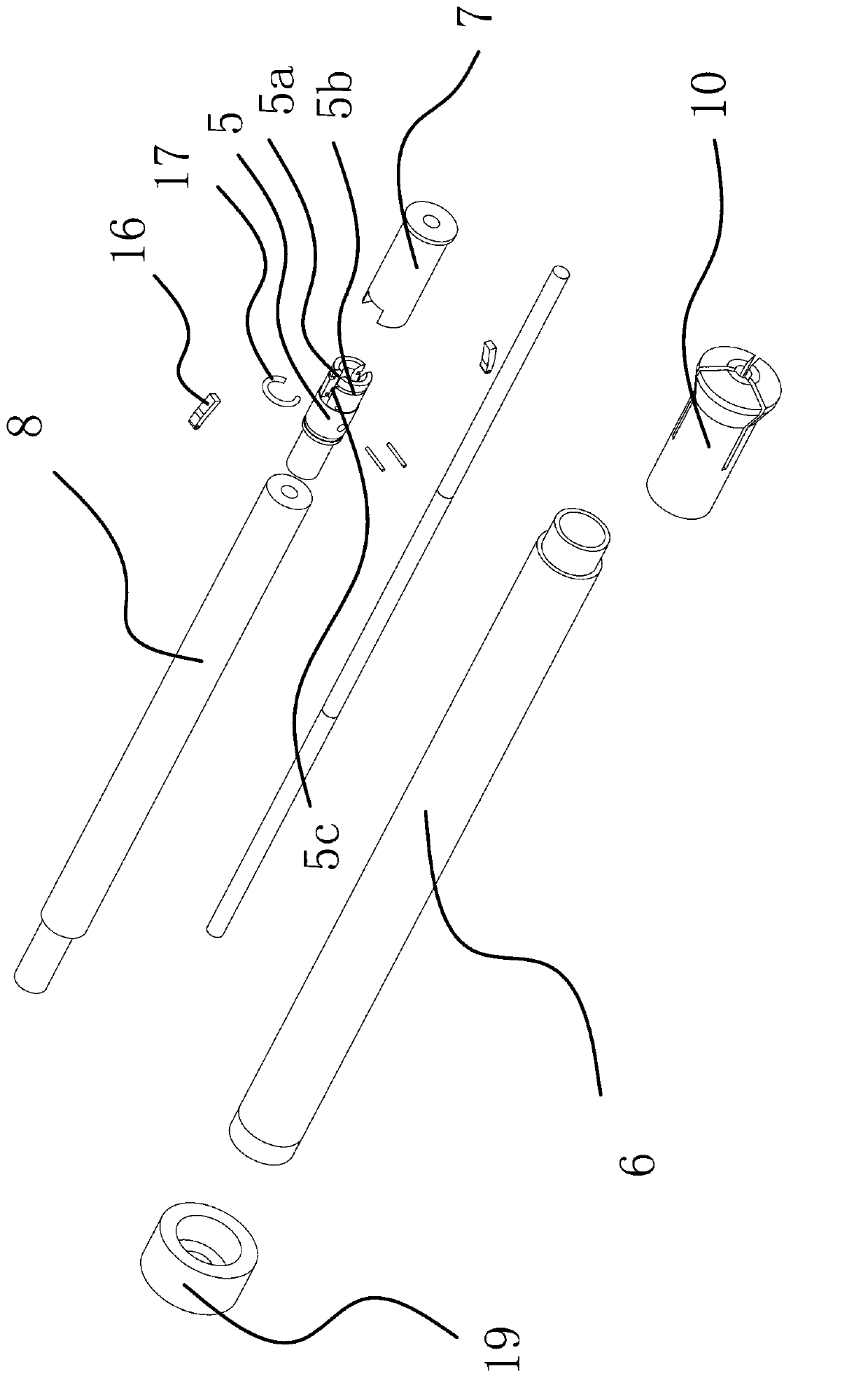
[0043] The structure and principle of this embodiment are basically the same as that of Embodiment 1, the difference is that: Figure 5 As shown, a strip-shaped installation hole 6a is opened on the outer wall of the clamping tube 6 in the axial direction, and bolts 21 for fixing the clamping tube 6 and the positioning seat 5 are inserted through the strip-shaped mounting hole 6a. This structure The front guide pipe 7 can be directly omitted, and since the distance between the front end of the collet 10 and the positioning seat 5 cannot be greater than the length of the shaft, the positioning seat 5 can be adjusted at any time according to the length of the shaft through the strip-shaped mounting hole 6a The installation position of the positioning seat 5 on the clamping tube 6 eliminates the need to replace the entire clamping tube 6, which is highly practical.


PUM


Abstract

The invention provides a full-automatic numerically-controlled machine tool for shafts, and belongs to the technical field of machinery. The full-automatic numerically-controlled machine tool for the shafts solves the problems that an existing numerically-controlled machine tool for the shafts is low in efficiency because feeding is low in speed, and feeding and blanking are separately carried out. The full-automatic numerically-controlled machine tool for the shafts comprises a working platform, a main machine, a front rack and a rear rack, wherein a material box is installed on the upper side portion of the front rack, a material conveying channel is formed in the front rack, a feeding device is installed on the front rack, a material receiving device is installed on the rear rack, a clamping stay tube is arranged in a spindle, a collet is installed at the front end of the clamping stay tube, a material leading base is installed on the working platform, a double-arm mechanical claw is arranged on the material leading base, a material leading device is arranged between the material leading base and the material receiving device, the material leading device and the spindle are arranged on the same axis line, a locating base is installed in the clamping stay tube, a locating mechanism is installed in the locating base, and a shaft arranged in the locating base can only pass through the locating mechanism under the action of external force. The full-automatic numerically-controlled machine tool for the shafts has the advantages that working efficiency is high, location is accurate, and feeding and blanking are synchronously carried out.

Description

technical field [0001] The invention belongs to the technical field of machinery and relates to a numerically controlled machine tool, in particular to a fully automatic numerically controlled machine tool suitable for machining shafts. Background technique [0002] At present, the processing of bearing bar materials is done manually, and the workpiece is clamped manually. The labor intensity of the workers is extremely high. After one shift, the operator needs to carry several tons of bar materials. Not only the physical strength of the workers is tested, but also Labor efficiency is difficult to guarantee, and product quality fluctuates greatly. Therefore, production tasks are often not completed on time, which affects the economic benefits of the enterprise. [0003] For this reason, the applicant applied for "a fully automatic CNC lathe" (authorized announcement number: CN202606871U) on May 31, 2012. Frame and rear frame, the upper side of the front frame is equipped wi...

Claims


Application Information

Patent Timeline
Patent Type & Authority Applications(China)
IPC IPC(8): B23Q7/04B23Q7/06B23Q7/08B23B15/00
Inventor 朱建群
Owner 宁波宫铁智能科技有限公司
Why Eureka
Try Eureka