Quick replacement method for movable pulley blocks and wire ropes in cranes

A technology of movable pulley block and steel wire rope, which is applied in the direction of clockwork mechanism and hoisting device, can solve the problems of low degree of automation, large amount of manual labor, long time consumption, etc., and achieve the goal of improving safety, saving time and saving cost Effect

Inactive Publication Date: 2013-09-04
JIGANG GRP
View PDF7 Cites 28 Cited by
  • Summary
  • Abstract
  • Description
  • Claims
  • Application Information

AI Technical Summary

Problems solved by technology

Among them, step 2) and step 3) are the tasks that consume the longest time and the largest amount of manual labor. It is necessary to manually pull out and thread the wire rope from the pulley repeatedly, and at the same time, it is accompanied by the work of manpower dragging the wire rope. The increase of the magnification will increase the amount of manual labor
[0003] The announcement date is May 5, 2010, and the announcement number is CN101700858A Chinese patent, which discloses a "coiled steel wire rope replacement method", which includes preparing, cutting off the old steel wire rope, connecting the end of the new and old steel wire rope, and fixing the new steel wire rope. The two ends and other steps are characterized by first dividing the old steel wire rope into two, and secondly connecting a section of the old steel wire rope with the new steel wire rope and guiding the new steel wire rope to be wound on the movable pulley block and the fixed pulley block under the action of the tension of the drum, and then fixing the new one. The two ends of the wire rope realize the semi-automatic replacement of the wire rope. Compared with the traditional method of replacing the wire rope, it has the advantages of simple operation, time saving, fewer operators, and high safety. However, this method still has the following problems: 1) This method only involves the replacement of the steel wire rope, and does not involve the problem of how to replace the entire movable pulley block; 2) The operation of dividing the steel wire rope into two and pulling out the other half of the waste steel wire rope from the pulley block has a low degree of automation

Method used


Image

  • Quick replacement method for movable pulley blocks and wire ropes in cranes
  • Quick replacement method for movable pulley blocks and wire ropes in cranes
  • Quick replacement method for movable pulley blocks and wire ropes in cranes

Examples


Embodiment Construction

[0009] The specific embodiments of the invention will be described below with reference to the drawings.

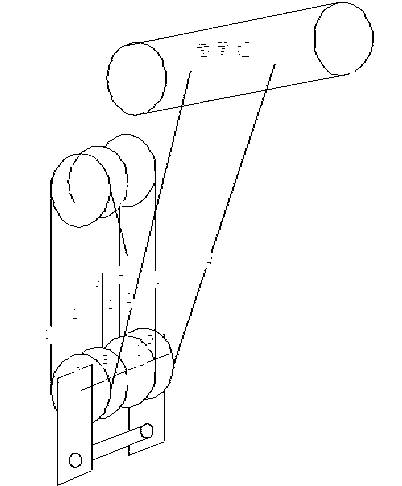
[0010] As attached figure 1 As shown, the old movable pulley block to be replaced is first dropped to a suitable position, and the lifting system is operated to keep the wire rope falling until the last two turns of the wire rope wound on the drum. figure 1 Middle 1, 2, 3, 4 are wire ropes wound in different movable pulleys. A, B, C, D indicate movable pulleys. The wire rope 1 descends from the drum and enters the movable pulley A, and then winds up into the fixed pulley, and then winds down to enter the movable pulley B. The movable pulley C is a reversing movable pulley. The wire rope enters the fixed pulley from the right side of the movable pulley C upwards, and then from The left side winds down and enters the movable pulley D, and the right side of the driven pulley D enters the other side pressure plate of the drum. This is the winding method of the entire wire rope o...


PUM


Abstract

The invention discloses a quick replacement method for movable pulley blocks and wire ropes in cranes. The method includes: 1, lowering an old movable pulley block to a proper position; 2, cutting off an old wire rope and re-setting a wire rope; 3, welding the old wire rope; 4, firmly welding the end of the new wire rope to the end of the old wire rope; 5, positively rotating a reel to wind the wire ropes; 6, cutting off a soldering point; 7, removing the old wire rope thoroughly; and 8, using another lifting system to drive and lift the two ends of the new wire rope pulled to the movable pulley block to the reel, and pressing the two ends of the wire rope into a pressure plate to end the replacement process. The method has the advantages of labor saving, simplicity in operation, and high automation level.

Description

Technical field [0001] The invention relates to the technical field of hoisting and transporting machinery, in particular to a method for quickly replacing a common bridge gantry crane movable pulley block and a steel wire rope. Background technique [0002] Bridge gantry cranes are indispensable logistics and transportation equipment for all kinds of production enterprises, and the replacement of their movable pulleys is also an important part of the daily maintenance of this type of equipment. The traditional replacement procedure is divided into the following steps: 1) Choose an appropriate position to drop the hook and uncover the wire rope heads at both ends of the double drum pressure plate; 2) Follow the wire rope heads in order from the movable pulley and the fixed pulley in the pulley block Pull out; 3) Manually thread the new wire rope into the new movable pulley block in the correct order, and then manually lift the wire rope head to the fixed pulley block and wind it ...

Claims


Application Information

Patent Timeline
Patent Type & Authority Applications(China)
IPC IPC(8): B66D1/28
Inventor 李玉杰王桂青李丙玉郑长山
Owner JIGANG GRP
Why Eureka
Try Eureka