An Electrode Arrangement Method for Downhole DC Advance Detection

A technology of advanced detection and electrode arrangement, applied in the field of electric and electromagnetic exploration, can solve the problems of not being successful, not considering the lateral perception ability of the driving face, and heavy workload, so as to avoid misjudgment and avoid massive model simulation.

Active Publication Date: 2015-11-04
JIANGSU UNIV
View PDF6 Cites 0 Cited by
  • Summary
  • Abstract
  • Description
  • Claims
  • Application Information

AI Technical Summary

Problems solved by technology

This arrangement method is easily affected by the abnormal body in the rear, and the detection accuracy is low, which often leads to misjudgment; or the transmitting and receiving electrodes are placed on the excavation surface, which avoids the influence of abnormal objects in the rear, but the longitudinal detection distance is very small, and the leading position is lost. Meaning of detection
The detection field of view of these two electrode layout methods is relatively narrow, and the lateral perception ability beyond the excavation surface is not considered;
[0005] (2) In the process of designing an electrode layout that meets the requirements, although three-dimensional numerical simulation can be a powerful tool for electrode layout design in advance detection, DC detection can have an infinite variety of electrode combinations. To discover the way, there are bound to be an infinite variety of models to be calculated, resulting in a huge workload and may not be successful

Method used


Image

  • An Electrode Arrangement Method for Downhole DC Advance Detection
  • An Electrode Arrangement Method for Downhole DC Advance Detection
  • An Electrode Arrangement Method for Downhole DC Advance Detection

Examples


Embodiment Construction

[0033] The technical solution of the present invention will be described in further detail below in conjunction with the accompanying drawings.

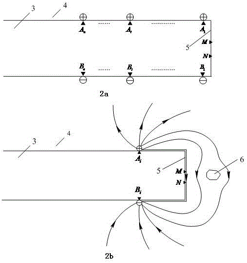
[0034] The dipole-dipole arrangement is used to realize the detection directly in front of the excavation face.

[0035] According to the placement method of the receiving electrode described in the technical scheme, the receiving electrode MN is placed on the excavation surface, see figure 2 The location of the MN in ;

[0036] According to the method of noise measurement in the signal-to-noise ratio described in the technical plan, the noise signal level is first measured by receiver air mining under the condition of no emission; The axis is in the opposite direction, and the interval required by the longitudinal resolution is set to move at 2m; according to ② in the technical plan, when the signal received by the receiving electrode is less than 3 to 5 times the noise, or the signal is less than the sensitivity of the receiver, ...


PUM


Abstract

The invention discloses a method for designing an underground direct current advanced detection device. The method comprises steps of putting receiving electrodes at a heading face and nearby areas, moving an emitting electrode from the heading face to a reverse direction along a roadway at an interval which is required by longitudinal resolution requirements, and when the influences of the roadway are ignored, forming a reverse mirror-image relationship between the position of the emitting electrode and an advanced detection distance and the heading face. A wide visual field is provided for advanced detection through utilizing combinations of different types of devices and electrode arrangement modes in a narrow roadway space. The method for guiding electrode combination is provided so as to prevent a huge amount of model calculations in a design. By utilizing the method, the influences of anomalous objects behind an existing device and misjudgment caused by the influences are avoided; a long-distance advanced detection capability is obtained; practical standards are provided for judging the maximum detection distance according to the sensitivity and signal to noise ratio of a receiver; and according to the method, an advanced detection mode for special requirements can be developed. The method can be widely applied to underground direct current electrical method advanced detection.

Description

technical field [0001] The invention belongs to the field of electrical and electromagnetic prospecting, and in particular relates to an underground direct-current advanced detection technology. Background technique [0002] The underground direct current method for advanced detection is an advanced detection method commonly used in coal mines. Especially when drilling detection may cause water inrush, cost, construction period, other methods are interfered by metal components, electromagnetic noise, or geophysical conditions are not met, the direct current method becomes the last means of advanced detection. The traditional DC advanced detection method mostly adopts a single-stage-dipole arrangement, and the transmitting electrode is placed near the excavation surface, and the receiving electrode is moved away from the excavation surface, in an attempt to obtain a longer-distance advanced detection capability. [1] . In fact, the potential anomalies of geological anomalies...

Claims


Application Information

Patent Timeline
Patent Type & Authority Patents(China)
IPC IPC(8): G01V3/22
Inventor 闫述吴巧郑吉
Owner JIANGSU UNIV
Why Eureka
Try Eureka