Construction method of multidirectional through concrete filled steel tubular column beam joint provided with steel corbels and ring beam

A technology of concrete filled steel tube and construction method, which is applied in the direction of construction and building structure, can solve problems such as poor seismic performance, and achieve the effects of improving the strength of ring beams, reducing welding workload and shortening construction period.

Active Publication Date: 2015-04-01
TAIXING FIRST CONSTR INSTALLATION
View PDF5 Cites 0 Cited by
  • Summary
  • Abstract
  • Description
  • Claims
  • Application Information

AI Technical Summary

Problems solved by technology

[0005] In order to solve the brittle strengthening of the joints in the prior art that the frame beam is directly connected to the steel pipe column radially through the steel corbel, and the frame beam is supported by the ring steel corbel through the ring beam, and the stressed main beam of the frame beam passes through the steel column , the problem of poor seismic performance, the invention provides a multi-directional through-hole steel that does not require on-site assembly, has a convenient, safe, and low-cost construction method, and can take into account the density of steel bars at the connection nodes between frame beams and steel pipe columns and the force of ring beams supporting frame beams Construction method of corbel, ring beam, steel tube concrete column beam joints

Method used


Image

  • Construction method of multidirectional through concrete filled steel tubular column beam joint provided with steel corbels and ring beam

Examples


Embodiment Construction

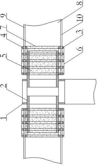
[0022] The present invention will be further described below in conjunction with drawings and embodiments.

[0023] figure 1 As shown, a multi-directional steel corbel, ring beam, steel pipe concrete column beam joint includes a plurality of steel corbels 2 and ring beams radially connected to the steel pipe column 1, the steel corbel 2 is I-shaped, and the The inner end of a steel corbel 2 penetrates into the steel pipe column 1 and is welded to each other in the steel pipe column, and the outer ends of a plurality of steel corbels 2 are pierced into the ring beam, and the ring beam includes a ring beam skeleton and a concrete ring beam inner core 5 , the ring beam skeleton is composed of two layers of ring beam bottom bars 3, two layers of ring beam top bars 4 and ring beam stirrups 7, the multiple steel rings of each layer of ring beam bottom bars 3 are concentric and in the same plane, and each layer of ring beams The multiple reinforcement circles of the bottom reinforce...


PUM


Abstract

The invention relates to a construction method of a multidirectional through concrete filled steel tubular column beam joint provided with steel corbels and a ring beam. The joint comprises a plurality of steel corbels and the ring beam, wherein the steel corbels are radially connected to a steel tubular column; inner ends of the steel corbels penetrate through the steel tubular column and are mutually welded and connected in the steel tubular column, and outer ends of the plurality of steel corbels penetrate through the ring beam; the ring beam comprises a ring beam framework and inner concrete ring beam cores arranged in the ring beam framework; the ring beam framework comprises two layers of ring beam bottom ribs, two layers of ring beam top ribs and ring beam stirrups; a plurality of reinforcing steel bar rings of each layer of ring beam bottom ribs and each layer of ring beam top ribs are concentric, and are located on the same plane and bound by a plurality of stirrups; and the two layers of ring beam bottom ribs and the two layers of ring beam top ribs are bound by a plurality of the ring beam stirrups. The joint has the advantages that the joint is simple in structure, free of dense reinforcing steel bars and feeble fragile stress positions and stable in load transmitting, can safely and stably bear a frame beam, and is convenient to construct, short in period, low in cost and applicable to construction of high-rise and super high-rise buildings having multidirectional through concrete filled steel tubular column beam joints comprising steel corbels and ring beams.

Description

technical field [0001] The invention relates to a column-beam joint construction method, in particular to a construction method for pouring steel pipe concrete column-beam joints by using multi-directional piercing steel corbels and ring beams. Background technique [0002] The concrete-filled steel tube structure is a new composite structure formed by filling concrete into steel tubes. Since the steel tube concrete structure can more effectively utilize the respective advantages of steel and concrete, and at the same time overcome the shortcomings of the steel tube structure that is prone to local buckling, in recent years the steel tube concrete structure has been gradually used in building structures, especially in high-rise and super high-rise buildings. in structure. The design of joints between CFST columns and reinforced concrete beams directly affects the overall stiffness, mechanical performance and safety of the structure, and also affects the difficulty of constr...

Claims


Application Information

Patent Timeline
Patent Type & Authority Patents(China)
IPC IPC(8): E04B1/58
Inventor 陈钧颐吴艳宗连明周吉生赵建平
Owner TAIXING FIRST CONSTR INSTALLATION
Why Eureka
Try Eureka