Method, device and system for bandwidth allocation

A bandwidth allocation and bandwidth technology, applied in the field of communications, can solve problems such as bandwidth allocation lag, reducing line delay, and reducing the buffering requirements of optical network equipment.

Inactive Publication Date: 2016-09-28
王丽东
View PDF7 Cites 0 Cited by
  • Summary
  • Abstract
  • Description
  • Claims
  • Application Information

AI Technical Summary

Problems solved by technology

[0011] The embodiment of the present invention provides a method for bandwidth allocation, which solves the problem of bandwidth allocation lag in non-fiber-to-user scenarios, thereby reducing the buffering requirements of optical network devices and reducing line delays

Method used


Image

  • Method, device and system for bandwidth allocation
  • Method, device and system for bandwidth allocation
  • Method, device and system for bandwidth allocation

Examples


Embodiment Construction

[0113] The embodiment of the present invention provides a method for bandwidth allocation, which solves the problem of bandwidth allocation lag in non-fiber-to-user scenarios, thereby reducing buffer requirements of optical network equipment and reducing line delay. Embodiments of the present invention also provide corresponding equipment and systems. Each will be described in detail below.

[0114] The following will clearly and completely describe the technical solutions in the embodiments of the present invention with reference to the accompanying drawings in the embodiments of the present invention. Obviously, the described embodiments are only some, not all, embodiments of the present invention. Based on the embodiments of the present invention, all other embodiments obtained by those skilled in the art without creative efforts fall within the protection scope of the present invention.

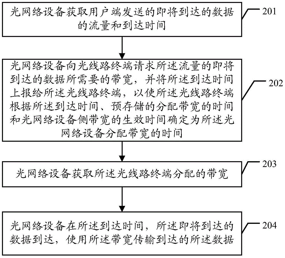
[0115] refer to figure 2 , an embodiment of the bandwidth allocation method provid...


PUM


Abstract

The invention discloses a bandwidth allocation method, which includes: acquiring the flow and arrival time of data about to arrive sent by a user terminal; The time for requesting the bandwidth from the optical line terminal, and when the time for requesting the bandwidth is reached, the bandwidth required for the incoming data of the traffic is requested from the optical line terminal; the bandwidth allocated by the optical line terminal is obtained; At the arrival time, the incoming data arrives, and the incoming data is transmitted using the bandwidth. The embodiments of the present invention also provide corresponding devices and systems. The technical solution of the present invention is that the optical network equipment can request bandwidth from the network line terminal in advance according to the arrival time of the upcoming data, thereby solving the problem of bandwidth allocation lag in the non-fiber-to-user scenario, thereby reducing the cache of the ONU. demand, reducing the line delay.

Description

technical field [0001] The present invention relates to the field of communication technologies, in particular to a method, device and system for bandwidth allocation. Background technique [0002] Passive optical network (PON) technology is a point-to-multipoint optical fiber access technology, refer to figure 1 , which consists of an optical line terminal (Optical Line Terminal, OLT) on the office side, an optical network unit (Optical Network unit, ONU) or an optical network terminal (Optical Network Terminal, ONT) on the user side, and an optical distribution network (Optical Distribution Network, ODN) )composition. [0003] There are mainly two types of connection modes in the passive optical network technology, one is Fiber To The Home (FTTH), and the other is non-FTTH. [0004] The difference between FTTH and non-FTTH is: [0005] The distance between the FTTH distribution point (distribution point, DP) and the user is still optical fiber, while the distance betwee...

Claims


Application Information

Patent Timeline
Patent Type & Authority Patents(China)
IPC IPC(8): H04L12/917H04Q11/00H04L47/76
CPCH04L12/4625
Inventor 隋猛何孝月石操
Owner 王丽东
Why Eureka
Try Eureka