Ultrasonic atomization spraying nozzle

A technology of ultrasonic atomization and nozzles, applied in the direction of spraying devices, liquid spraying devices, etc., can solve the problems of large particle size, increased water consumption, poor effect, etc., achieve fine water mist particles, slow down the flow rate of water mist, Easy to install and use

Inactive Publication Date: 2014-01-22
SUZHOU HUAAN MINING TECH
View PDF4 Cites 3 Cited by
  • Summary
  • Abstract
  • Description
  • Claims
  • Application Information

AI Technical Summary

Problems solved by technology

The low atomization rate means that the water mist particles are large. Therefore, ordinary low-pressure nozzles are used as dust removal facilities, which are the facilities with the worst effect.
[0004] Many places with serious dust pollution, such as coal mine underground working face, return air tunnel, coal washing plant, cement plant, power plant, etc., use ordinary low-pressure nozzles as dust removal facilities , in order to achieve the effect of dust reduction, increase the number of nozzles, increase the water consumption, the dust can only be reduced to a certain extent, the pollution still exists, and the excessive use of water causes the production to be passive, and the water flow becomes a disaster. In turn, the common low pressure nozzles are closed or intermittent Ordinary low-pressure nozzles with automatic switches can not achieve the ideal goal for dust control
[0005]Most of the nozzles currently used are single-fluid (liquid) nozzles. Due to the low water supply pressure (generally less than 10MPa), the particle size of the mist is large, which cannot be used for respirable dust. Play an effective role in dust suppression

Method used


Image

  • Ultrasonic atomization spraying nozzle

Examples


Embodiment Construction

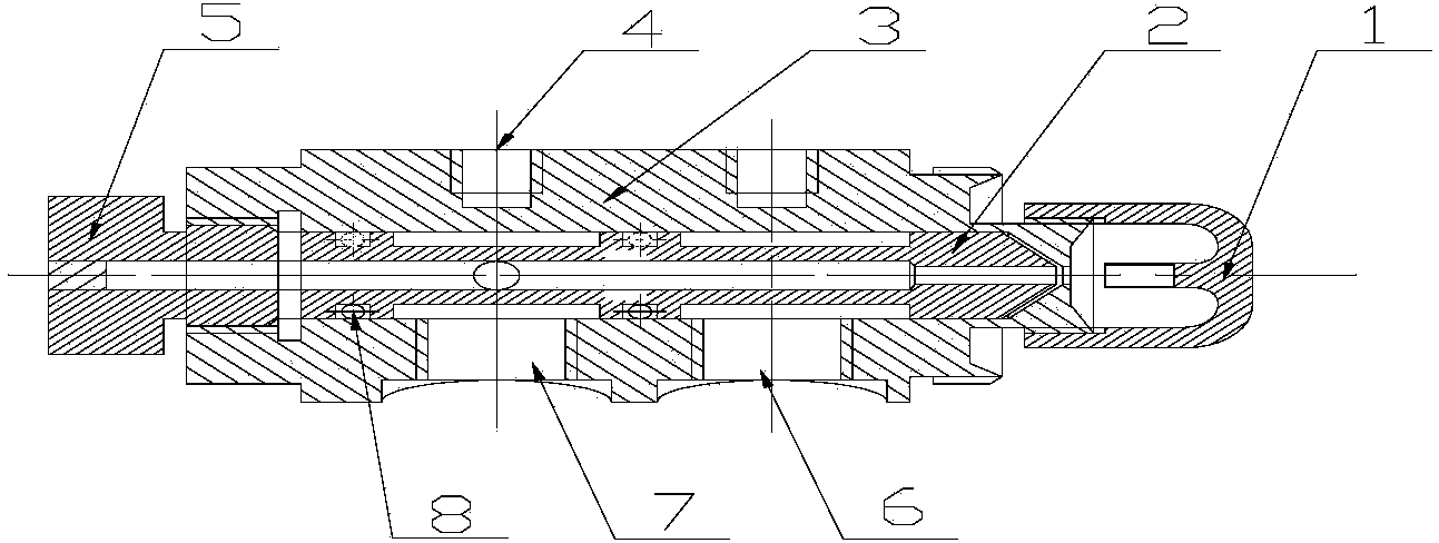
[0026] Ultrasonic impulse nozzle, including shell 3, seal 8, core 2, one end of the inner cavity of cylindrical shell 3 is open, and the other end is closed in a conical shape, only a small hole is left in the center, and the resonance of the gas mist emission device is provided. The cup 1 is fixed on the shell 3. The cylindrical core 2 is cylindrical at one end and conical at the other end. There is a very thin hollow channel in the center of the core 2. The hollow channel is closed at the cylindrical end and conical in shape. The end opening is connected to the outside air, and the core body 2 is inserted into its inner cavity from the open end of the shell body 3. The outer diameter of the core body 2 is slightly smaller than the inner diameter of the shell body 3, and the cone of the core body 2 is slightly smaller than the diameter of the cone-shaped closed end of the shell body 3. Holes, near the conical closed end of the shell 3 is provided with a water interface 6, near...


PUM


Abstract

The invention discloses an ultrasonic atomization spraying nozzle which comprises a shell, a seal and a core. An opening is formed in one end of an inner cavity of the cylindrical shell, and only a small hole is reserved in the middle of the other end of the inner cavity after the other end of the inner cavity is conically closed. A resonance cup provided with an aerial fog spreading device is fixed on the shell, one end of the cylindrical core is cylindrical, the other end of the cylindrical core is conical, a quite thin hollow channel is formed in the center of the core, the hollow channel is closed at the cylindrical end and open at the conical end to be connected with external air, the core is inserted into the inner cavity of the shell from the end, provided with the opening, of the shell, the outer diameter of the core is slightly smaller than the inner diameter of the shell, the cone of the core is slightly smaller than the small hole in the conical closed end of the shell, a water connector is formed in the position close to the conical closed end of the shell, an air connector is formed in the position close to the end, provided with the opening, of the shell, sealing grooves are formed in the positions, between the water connector and the air connector and between the air connector and the end, provided with the opening, of the shell, of the core, the seal is installed on the sealing grooves, an airtight space is formed by the shell, the seal and the core, and an air guiding hole is formed in the wall, in the airtight space, of the core so that the space can be communicated with the hollow channel of the core.

Description

technical field [0001] This application relates to the field of mine dust removal equipment Background technique [0002] The nozzle is to convert the water flow into water mist. Water mist is a resource needed in the workplace, and most of it is used to reduce dust. At present, most nozzles are ordinary low-pressure nozzles. Whether it is a single-head or multi-head nozzle, no matter what kind of water guide core it contains, there are low atomization rate, low kinetic energy of water mist, and relatively small atomization cone angle. Small size, high resource consumption and other issues. [0003] There is a direct relationship between water mist particles and dust removal efficiency, that is, the smaller the water mist particles, the higher the dust removal efficiency. The low atomization rate means that the water mist particles are large. Therefore, ordinary low-pressure nozzles are used as dust removal facilities, which are the facilities with the worst effect. [00...

Claims


Application Information

Patent Timeline
Patent Type & Authority Applications(China)
IPC IPC(8): B05B17/06
CPCB05B17/0692
Inventor 谢耀社
Owner SUZHOU HUAAN MINING TECH
Why Eureka
Try Eureka