Automatic product extracting jig

An automatic and jig technology, applied in the field of injection molding equipment, can solve the problems of small size, bumps and crushes, and relatively high dimensional accuracy requirements, and achieve the effects of automatic control, reduction of product costs, and avoidance of bumps and falls.

Active Publication Date: 2014-01-22
CHINA LTD
View PDF6 Cites 6 Cited by
  • Summary
  • Abstract
  • Description
  • Claims
  • Application Information

AI Technical Summary

Problems solved by technology

This way of taking out is suitable for products with a rough appearance, because the products fall together, which is prone to the risk of being bruised and crushed
[0007] At the same time, due to the relatively small size of the current products, the requirements for dimensional accuracy are relatively high, and one mold has 16 cavities. The 16-cavity products must be shipped in separate cavities. The product is not allowed to have bruises and garbage. Use the traditional removal method Product production requirements that cannot be met by methods

Method used


Image

  • Automatic product extracting jig

Examples


Embodiment 1

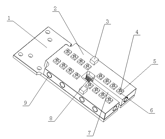
[0023] as attached figure 1 As shown, a product automatic suction fixture includes an air circuit board 2, the upper end surface of the air circuit board 2 is provided with a suction and blowing device, and the air circuit board 2 is provided with an air circuit 9, and the air circuit 9 and the suction and blowing device connected. The air circuit board 2 is provided with an opening 7, the opening 7 extends to the center of the air circuit board 2, and the width of the opening at the center is greater than the width of the opening at the edge.

[0024] The invention is specially matched with the manipulator in the injection molding machine. It can be seen from this that the manipulator is fixedly connected to the lower end surface of the air circuit board 2, and the manipulator clip 8 on the manipulator is located in the opening 7 and is in the center of the air circuit board 2 Location.

[0025] The present invention is combined with vacuum fan, electromagnetic valve, vacu...

Embodiment 2

[0030] The rest is the same as that of Embodiment 1, the difference is that the suction and blowing device includes several installation seats 6 symmetrically installed on the air circuit board 2, and the center position of the end surface of the installation seats 6 is provided with a top post 4, Suction and blowing holes 5 are evenly distributed around, and the suction and blowing holes 5 communicate with the air passage 9 .

[0031] In this embodiment, the number of mounting seats 6 is set according to actual needs. Generally, there are 16 mounting seats 6 installed symmetrically on the upper end surface of the air circuit board 2 . Suction and blow holes 5 are uniformly arranged around the top column 4 .

[0032] The function of the top column is to prevent the product from directly covering the suction and blowing holes 5 when the product is sucked, causing the suction and blowing holes 5 to fail to inhale, or to inhale poorly.

Embodiment 3

[0034] The rest is the same as the embodiment 2, except that several fine positioning blocks 3 are provided on the edge of the air circuit board 2 .

[0035] The number and installation positions of the fine positioning blocks 3 are determined according to the actual needs of the product. In this embodiment, there are two fine positioning blocks 3 , which are respectively installed relative to the center of the air circuit board 2 . The function of the fine positioning block 3 is to accurately locate the position of the product, so that it can be accurately delivered to the predetermined position when it is delivered.


PUM


Abstract

The invention discloses an automatic product extracting jig which comprises a gas path plate. The automatic product extracting jig is characterized in that a sucking and blowing device is arranged at the upper end face of the gas path plate, a gas path is arranged in the gas path plate and is communicated with the sucking and blowing device, and an opening is formed in the gas path plate and extends to the center of the gas path plate. Furthermore, the sucking and blowing device comprises a plurality of installing bases symmetrically arranged on the gas path plate, a support pillar is arranged at the center of the end face of the installing base, sucking and blowing holes are uniformly formed around the support pillar; and the sucking and blowing holes are communicated with the gas path. The automatic product extracting jig is matched with a vacuum fan, an electromagnetic valve, a vacuum switch valve and a controller to form an automatic product extracting system. Due to the adoption of such design, the automatic control of the whole process is realized, the manual operation is not needed, and the product cost is lowered. Meanwhile, actions in a whole product sucking and charging process are gentle, and accidents such as collision, breakage and the like of products are avoided.

Description

technical field [0001] The invention belongs to the field of injection molding equipment, and in particular relates to a jig for automatically sucking out products. Background technique [0002] Injection molding machine is also known as injection molding machine or injection machine. It is the main molding equipment for making thermoplastics or thermosetting materials into various shapes of plastic products with plastic molding molds. Divided into vertical, horizontal, all-electric. The injection molding machine heats the plastic, applies high pressure to the molten plastic, and makes it shoot out to fill the mold cavity. In the injection molding machine, the manipulator takes out the injection molded product in the following two ways: [0003] The first one: the product is clamped by the manipulator and placed on the conveyor belt, and then the product is taken down manually, and the sprue is cut off and placed in the blow molding tray. [0004] This kind of product re...

Claims


Application Information

Patent Timeline
Patent Type & Authority Applications(China)
IPC IPC(8): B29C45/43
CPCB29C45/43
Inventor 李磊刘国权
Owner CHINA LTD
Why Eureka
Try Eureka