Dynamic mixer

A dynamic mixer and dynamic technology, applied in the direction of fluid mixer, mixer, mixer with rotary stirring device, etc., can solve the problems of unwanted generation and disadvantage, and achieve the reduction of waste share, filling amount, and reduction The effect of production costs

Active Publication Date: 2014-01-22
MEDMIX SWITZERLAND AG
View PDF12 Cites 12 Cited by
  • Summary
  • Abstract
  • Description
  • Claims
  • Application Information

AI Technical Summary

Problems solved by technology

This arrangement serves to retard the rotation of the medium in the mixer, which may be detrimental to the mixing of components that harden quickly
With this arrangement it may not be desirable to produce a conveying effect as before, since the opposite effect is sought

Method used


Image

  • Dynamic mixer
  • Dynamic mixer
  • Dynamic mixer

Examples


Embodiment Construction

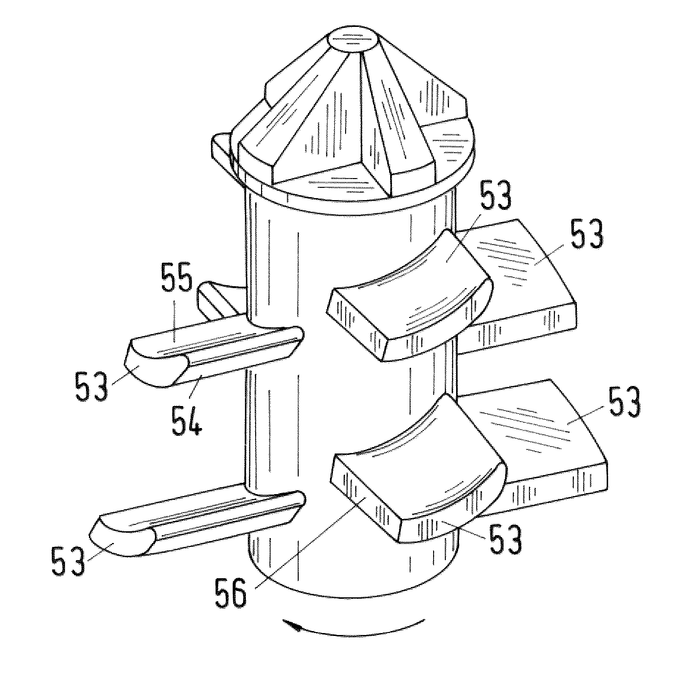
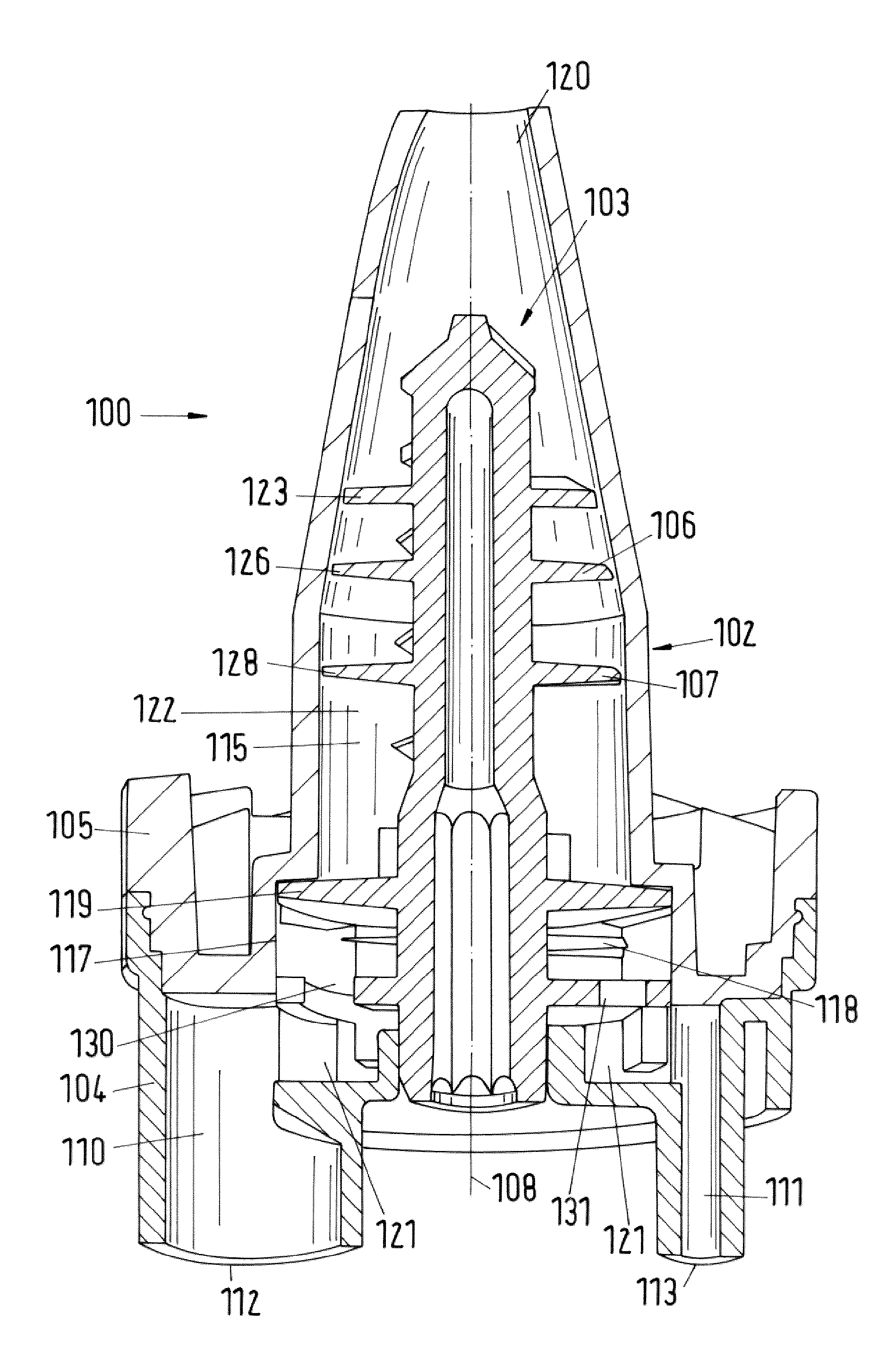
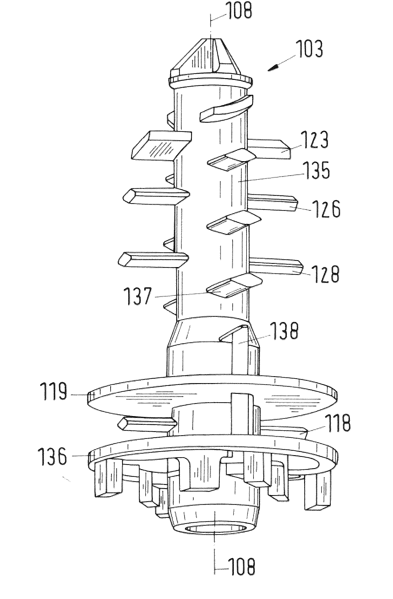
[0038] figure 1 A dynamic mixer for multiple fluid components is shown. The dynamic mixer 1 has a housing 2 and a rotor element 3 arranged rotatably about a rotor axis 8 in the housing 2 . In this embodiment, the housing 2 is constructed in two subsections, comprising a first housing subsection 4 and a second housing subsection 5 in which there is an inlet for the components, The second housing subsection is used to produce a mixture from a plurality of fluid components. As soon as the rotor element 3 is accommodated in the second housing part 5 , the first housing part is connected to the second housing part by means of a snap-in connection, a snap connection or a welded connection. The first housing subsection 4 has at least one inlet 12 , 13 for each component. The inlets 12 , 13 can have different diameters depending on the desired mixing ratio of the components. The inlets open into corresponding inlet channels 10 , 11 which are arranged in the first housing subsecti...


PUM


Abstract

The invention relates to a dynamic mixer (1, 100) for a plurality of fluid components, comprising a housing (2, 102) and a rotor element (3, 103) which is rotatably arranged in the housing, wherein the housing comprises a respective inlet opening (12, 13, 112, 113) at least for each component, and at least one outlet opening (20, 120). An annular space is provided between the rotor element and the housing, in which annular space a mixing element (7, 107) connected to the rotor element is arranged. The mixing element is provided with a blade element (23, 43, 53) configured as a guide element for conveying the components from the inlet opening to the outlet opening. The blade element (23, 43, 53) is a guide element and comprises a guide surface (25, 45, 55) of concave curved shape with respect to the outlet opening (20, 120). The blade element is further removed from the outlet opening (20, 120) on the upstream side thereof than on the downstream side thereof.

Description

technical field [0001] The present invention relates to a dynamic mixer. Background technique [0002] A dynamic mixer is known from WO 2007 / 041878 for mixing components with different volume fractions, in particular for producing molding materials for dental impressions. In the inner chamber of the mixer housing there is arranged a prechamber in which the mixing rotor has a dispersion for dispersing the components about its axis of rotation in order thereby to achieve the correct mixing ratio between these components and Avoid air inclusions. The premixed components then pass through at least one through opening into the main chamber in order to be able to mix thoroughly. [0003] Especially when the mixing ratio of viscous or pasty components is high, it is particularly difficult to constantly maintain the correct mixing ratio and to obtain good mixing results. Mixing is generally achieved by shear forces, wherein the components are squeezed by a mixer. The mixer has a...

Claims


Application Information

Patent Timeline
Patent Type & Authority Applications(China)
IPC IPC(8): B01F7/00B01F13/00A61C9/00
CPCA61C9/0026B05C17/00566B01F25/4319B01F25/431B01F25/431971B01F27/0724B01F27/0722B01F27/1121B01F27/092B01F27/1123B01F27/1125B01F27/2712B01F27/192B01F33/5011B01F33/8212B01F33/821B01F2101/19B01F2101/2305A61C9/00B01F27/00B01F33/00B01F27/11
Inventor V.林内A.海默尔F.赫斯勒
Owner MEDMIX SWITZERLAND AG
Why Eureka
Try Eureka