

Water seal ring of mechanical seal gland
A technology of mechanical sealing device and water sealing ring, applied in mechanical equipment, machine/engine, liquid fuel engine, etc., can solve problems such as unsatisfactory sealing effect and leakage of quenching liquid, achieve reasonable structure, improve sealing ability, installation and use handy effect
Inactive Publication Date: 2014-02-26
DANDONG COLOSSUS GROUP
View PDF4 Cites 0 Cited by
- Summary
- Abstract
- Description
- Claims
- Application Information
AI Technical Summary
Problems solved by technology
Because there is a gap between the water seal ring and the shaft sleeve, the quenching liquid can easily leak out of the pump through the gap, and the sealing effect is not ideal
Method used
View moreImage
Smart ImageViewing Examples

Examples
Embodiment Construction
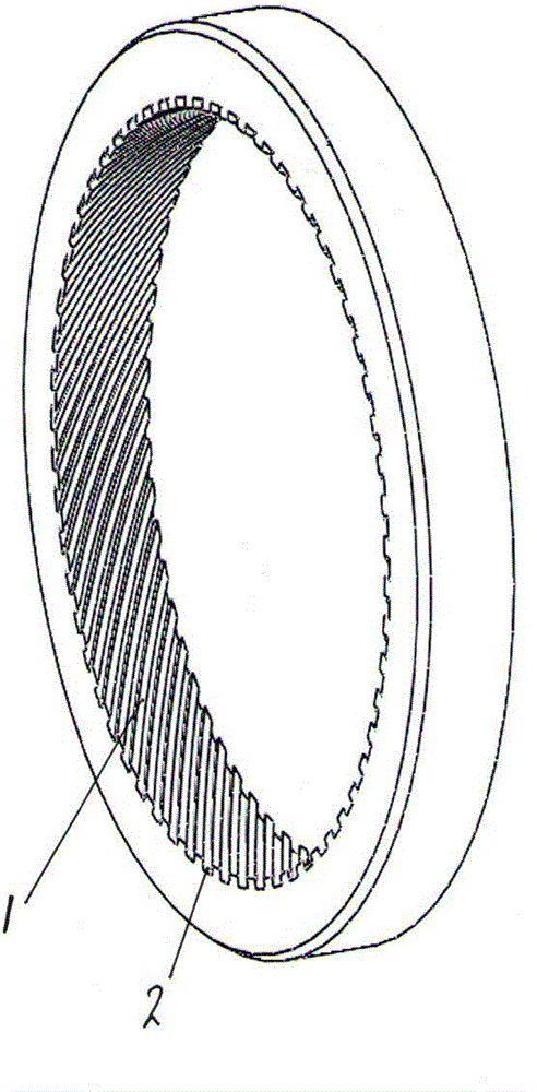
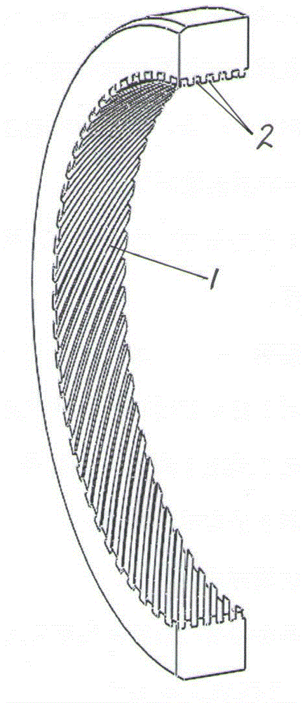
[0011] The water seal ring of the gland of the mechanical seal device of the present invention is provided with a spiral groove 2 on the inner ring surface 1 of the water seal ring to form a spiral pumping ring.
Login to View More PUM
 Abstract
A water seal ring of a mechanical seal gland is characterized in that spiral grooves are formed in the inner annular face of a water seal ring, and a spiral pump ring is formed. The water seal ring is reasonable in structure, good in sealing effect and convenient to mount and use, and additional space is omitted.
Description
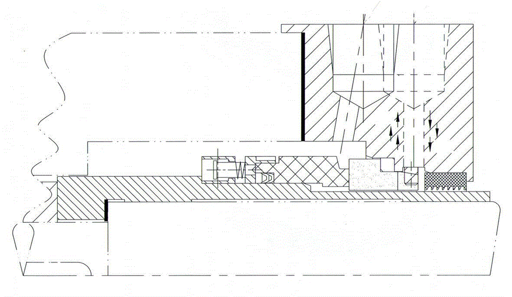
technical field [0001] The invention relates to a water seal on a mechanical seal gland. To improve the sealing effect of the water seal on the gland. Background technique [0002] There is a water seal on the gland of the mechanical seal device, especially in the API682-62 scheme, the water seal is a very commonly used auxiliary sealing element. The water seal on the gland of the traditional mechanical seal device is to set up a labyrinth groove or throttle groove on the inner ring surface of the water seal ring to reduce the leakage of quenching water. When the pump shaft is running, a labyrinth groove and shaft Or the shaft sleeve cooperates, the shaft sleeve rotates to drive the quench liquid to rotate to generate centrifugal force, and cooperates with the resistance of the throttle ring groove to the liquid to prevent the quench liquid from leaking outward. Because there is a gap between the water seal ring and the shaft sleeve, the quench liquid can easily leak out...
Claims
Login to View More Application Information
Patent Timeline
 IPC IPC(8): F04D29/12
Inventor关键于平超刘铁峰何德贵王慧许斌马宇滕朋唐志坚
OwnerDANDONG COLOSSUS GROUP