

Electromagnetic circuit breaker delay tube with leakage-proof function
A technology of delay tube and circuit breaker, applied in electromagnetic relays, electromagnetic relay details, circuits, etc., can solve the problems of poor connection strength of sealing joints of delay tube components, increase of delay oil temperature, product damage and failure, etc. Achieve the effect of improving service life and practicability, relieving pressure and reducing extrusion
- Summary
- Abstract
- Description
- Claims
- Application Information
AI Technical Summary
Problems solved by technology
Method used
Image

Examples
Embodiment Construction
[0019] In order to enable those skilled in the art to better understand the technical solution of the present invention, the present invention will be described in detail below in conjunction with the accompanying drawings. The description in this part is only exemplary and explanatory, and should not have any limiting effect on the protection scope of the present invention. .
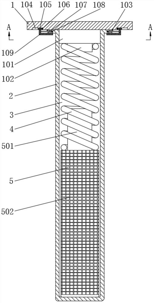
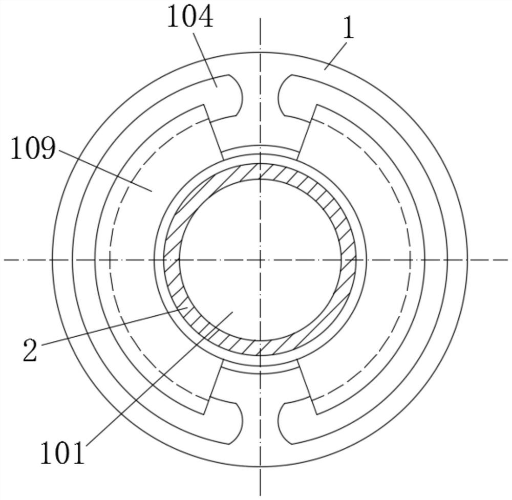
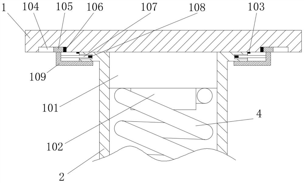
[0020] Such as Figure 1-Figure 3 As shown, the specific structure of the present invention is: a delay tube for an electromagnetic circuit breaker with a leak-proof function, comprising a fixed iron core 1 and a delay tube 2, the delay tube 2 is a hollow tubular structure, and the fixed iron core The boss 101 in the middle of the body 1 extends into the delay tube body 2 and is pressure-sealed with the inner wall of the delay tube body 2. The end of the boss 101 is provided with a first connecting column 102, and one end of the first connecting column 102 is connected to the compression spring 4 One ...
PUM
 Abstract
Description
Claims
Application Information