Backlight module

A backlight module and backlight technology, applied in optics, light guides, light sources, etc., can solve problems such as deformation of the light shielding cover, deformation and cracking of the light guide plate 13, and achieve the effect of improving quality and enhancing heat dissipation

A backlight module and backlight technology, applied in optics, light guides, light sources, etc., can solve problems such as deformation of the light shielding cover, deformation and cracking of the light guide plate 13, and achieve the effect of improving quality and enhancing heat dissipation

CN103672620AActive Publication Date: 2014-03-26CHANGSHA HKC OPTOELECTRONICS CO LTD

Image

  • Backlight module
  • Backlight module
  • Backlight module

Examples


Embodiment Construction

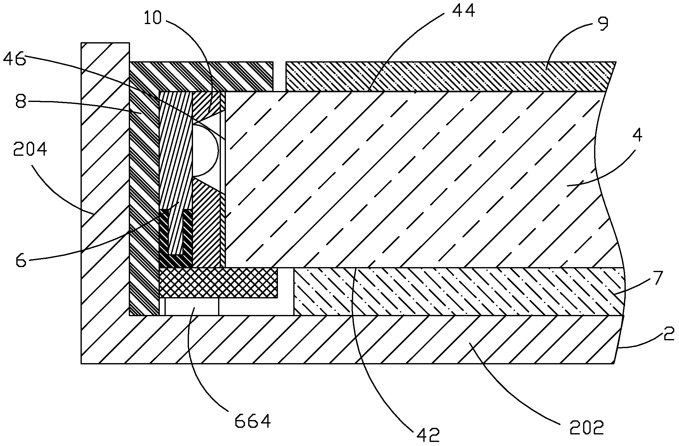
[0027] In order to further illustrate the technical means adopted by the present invention and its effects, the following describes in detail in conjunction with preferred embodiments of the present invention and accompanying drawings.

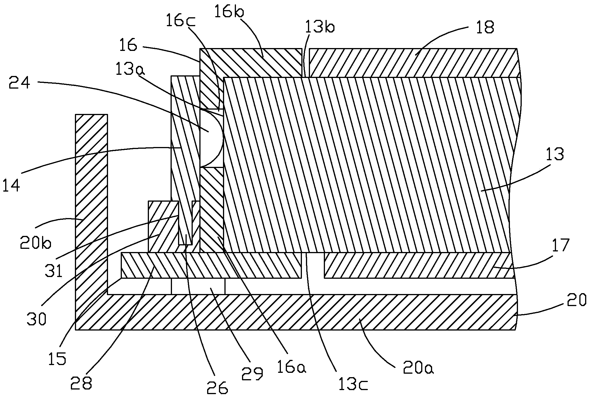
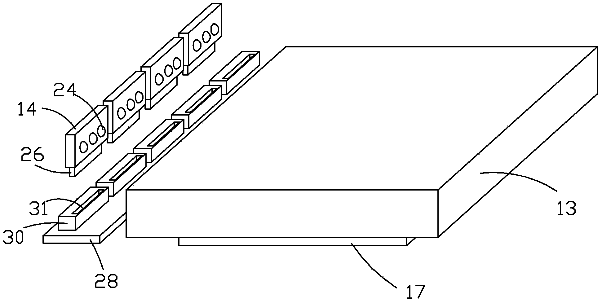
[0028] see image 3 , the present invention provides a backlight module, comprising: a backplane 2, a light guide plate 4 disposed in the backplane 2, a backlight source 6 disposed in the backplane 2 and located on one side of the light guide plate 4, a backlight source 6 disposed in the backlight 6 The shading cover 8 between the back plate 2 and the side reflector 10 arranged between the light guide plate 4 and the backlight 6, the light emitted by the backlight 6 directly enters the light guide plate 4 after being reflected by the side reflector 10, and Propagate in the light guide plate 4, and then transform the point light source into a surface light source.

[0029] Specifically, the back plate 2 includes a bottom plate 202 and several ...


PUM


Abstract

The invention provides a backlight module which comprises a back plate (2), a light guide plate (4), a backlight source (6), a light shield (8) and a side reflecting piece (10). The light guide plate (4) is arranged inside the back plate (2). The backlight source (6) is arranged inside the back plate (2) and located on one side of the light guide plate (4). The light shield (8) is arranged between the backlight source (6) and the back plate (2). The side reflecting piece (10) is arranged between the light guide plate (4) and the backlight source (6). The backlight source (6) comprises an LED substrate (62) and a plurality of LED lamps (64) installed on the LED substrate (62). The side reflecting piece (10) has elasticity. The side reflecting piece (10) is provided with a plurality of openings (102) corresponding to the LED lamps (64). The LED lamps (64) are contained inside the openings (102) and provide a light source for the light guide plate (4).

Description

technical field [0001] The invention relates to the field of plane display, in particular to a backlight module. Background technique [0002] Liquid Crystal Display (LCD) has many advantages such as thin body, power saving, and no radiation, and has been widely used, such as mobile phones, personal digital assistants (PDAs), digital cameras, computer screens or laptop screens Wait. [0003] Most of the liquid crystal display devices currently on the market are backlight liquid crystal display devices, which include a housing, a liquid crystal panel disposed in the housing, and a backlight module disposed in the housing. The structure of a traditional liquid crystal panel consists of a color filter substrate (Color Filter), a thin film transistor array substrate (Thin Film Transistor Array Substrate, TFT Array Substrate), and a liquid crystal layer (Liquid Crystal Layer) arranged between the two substrates. Its working principle is to control the rotation of the liquid cry...

Claims


Application Information

Patent Timeline
26 Mar 2014
Publication
CN103672620A
IPC
F21S8/00; F21V17/10; F21V13/12; F21V29/00; F21Y101/02; F21V29/50
CPC
G02B6/0031
Inventors
ไฟžๅˆš; ่งๅฎ‡ๅ‡