Transparent liquid crystal display panel and transparent display device

A transparent liquid crystal display and display device technology, applied in identification devices, nonlinear optics, instruments, etc., can solve problems such as limited anti-reflection effects, achieve the effects of preventing visual vertigo, reducing production difficulty, and controlling production costs

Inactive Publication Date: 2014-03-26
青岛斯博锐意电子技术有限公司
View PDF10 Cites 5 Cited by
  • Summary
  • Abstract
  • Description
  • Claims
  • Application Information

AI Technical Summary

Problems solved by technology

However, the use of this circular polarizing plate formed by PVA and λ / 4 plate adds a manufacturing process. At the same time, each additional layer of structure will inevitably bring about a light absorption, that is, an increase in the loss of transmitted light. Adding a backlight to the side for supplementary light, the anti-reflection effect of its single use is also very limited, and it is not an ideal anti-reflection solution

Method used


Image

  • Transparent liquid crystal display panel and transparent display device
  • Transparent liquid crystal display panel and transparent display device
  • Transparent liquid crystal display panel and transparent display device

Examples


Embodiment 1

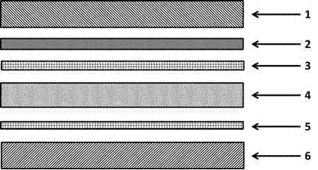
[0049] refer to figure 1 As shown, first, the present invention provides a transparent liquid crystal display panel, characterized in that, the transparent liquid crystal display panel includes a first optical deflection plate 1 , a liquid crystal layer 4 and a second optical deflection plate 6 . The liquid crystal layer sandwich 4 is arranged between the first optical deflection plate 1 and the second optical deflection plate 6; the liquid crystal layer 4 is a single-layer in-line liquid crystal layer; the first optical deflection plate 1 is on the surface in contact with the liquid crystal layer A color filter layer 2 and a first transparent electrode layer 3 are arranged in sequence; a second transparent conductive layer 5 is arranged on the surface of the second optical deflection plate 6 in contact with the liquid crystal layer.

[0050] refer to figure 2 In the present invention, the color filter layer structure is composed of a plurality of array color filter pixel ar...

Embodiment 2

[0058] On the basis of the solution in Embodiment 1, the pixel structure in the color filter layer is adjusted, and other corresponding structural settings and requirements are the same as those in Embodiment 1.

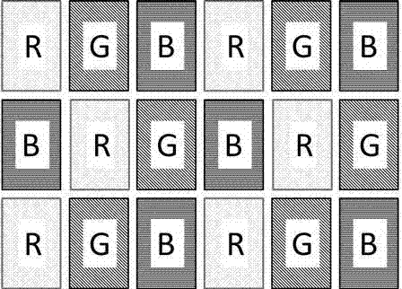
[0059] refer to Figure 4 In the present invention, the color filter layer structure is composed of a plurality of array color filter pixel areas, and each color filter pixel area is composed of a red sub-pixel area (represented by R in the figure), a green sub-pixel area (represented by G in the figure) and a blue sub-pixel area. The color sub-pixel regions (represented by B in the figure) are composed; and the sub-pixel regions of the same color are not arranged adjacently.

[0060] Specifically to the present embodiment, the order of the first row is: ...... RGBRGB ......; the order of the second row is ...... BRGBRG ......; the order of the third row is ...... GBRGBR ....... In the entire color filter layer, the horizontal sequence and the vertical sequence are ...

Embodiment 3

[0062] On the basis of the solution in Embodiment 1, the pixel structure in the color filter layer is adjusted, and other corresponding structural settings and requirements are the same as those in Embodiment 1.

[0063] refer to Figure 5 In the present invention, the color filter layer structure is composed of a plurality of array color filter pixel areas, each color filter pixel area is composed of a red sub-pixel area (represented by R in the figure), a green sub-pixel area (represented by G in the figure) and a blue sub-pixel area. The color sub-pixel regions (represented by B in the figure) are composed; and the sub-pixel regions of the same color are not arranged adjacently.

[0064] Specifically to this embodiment, the order of the first row is: ...RGBRGB...; the order of the second row is...GBRGBR...; the order of the third row is...BRGBRG.... In the entire color filter layer, the horizontal sequence and the vertical sequence are repeated in turn and so on. It shoul...


PUM

PropertyMeasurementUnit
thicknessaaaaaaaaaa
transparencyaaaaaaaaaa

Abstract

The invention discloses a transparent liquid crystal display panel and a transparent display device. Firstly, the invention provides the transparent liquid crystal display panel which comprises a first optical deflection piece, a liquid crystal layer and a second optical deflection piece, and is characterized in that the transparent liquid crystal panel further comprises a color filter layer, the color filter layer is composed of arrays of color filtering pixel regions, and each color filtering pixel region is composed of a red sub-pixel region, a green sub-pixel region and a blue sub-pixel region; sub-pixel regions in the same color are non-adjacent in arrangement. Secondly, the invention provides the transparent display device which comprises a box body, a light source and an inner decorating plate, and at least one side of the box body adopts the transparent liquid crystal display panel. The transparent liquid crystal display panel and the transparent display device employing the transparent liquid crystal display panel achieve transparent display in large size, wide colour range, high contrast ratio, high transparency, and high resolution ratio of true color imaging.

Description

technical field [0001] The present invention relates to a flat display panel and a display device, in particular to a transparent liquid crystal display panel and a transparent display device having the transparent liquid crystal display panel. Background technique [0002] With the increasing development of display technology, various new technologies are constantly emerging. Transparent display technology has attracted more and more attention due to its transparent display panel and its unique application. [0003] The core of the transparent display technology is the transparent display panel. The transparent display panel is a transparent panel that can display images. It is different from the traditional double-sided display technology. display device. When the transparent display panel is closed, the panel is like a piece of transparent glass; when it is working, the viewer can not only watch the content displayed on the display panel, but also see the objects and bac...

Claims


Application Information

Patent Timeline
Patent Type & Authority Applications(China)
IPC IPC(8): G02F1/1335G09F9/35
Inventor 杨涛
Owner 青岛斯博锐意电子技术有限公司
Why Eureka
Try Eureka